LNB V/H Voltage
- Thread starter RT-Cat
- Start date
- Latest activity Latest activity:
- Replies 66
- Views 14K
You are using an out of date browser. It may not display this or other websites correctly.
You should upgrade or use an alternative browser.
You should upgrade or use an alternative browser.
- Status
- Please reply by conversation.
I found some time. Resistor "trick" made no difference. On for about 3 seconds then drop off to no signal.
RT.
RT.
Measuring current on the RF side of the choke and expecting a "good" signal is not reliable. Even taking voltage readings there (coax) can load the front end and cause unpredictable results, especially on digital signals. If you can get to the traces, the best place to meter is on the regulator's (output) side of the RFC. If possible to access, cut the trace from the regulator output and get in series there. Use either of those points (ref gnd) for a voltage TP. You can always solderbridge the cut back together when you've fixed the problem.
I'd be curious to know what the control input voltage is doing during these tests. It does sound like the (TO220 case?) regulator is going into current limit mode for whatever reason. Are you certain it's the correct replacement device? Limiting can be causes by it overheating as well, or it being defective and acting as if it is overheating. Maybe you got a dud. Except for mil spec parts, new does not always mean good.
If the regulator's control input varies proportional to the "works for a bit then quits" cycles then the problem is before the regulator, possibly the driver transistor (likely another "chip" SMT 3 legged black square) is malfunctioning under load.
Best of luck getting it figured out.
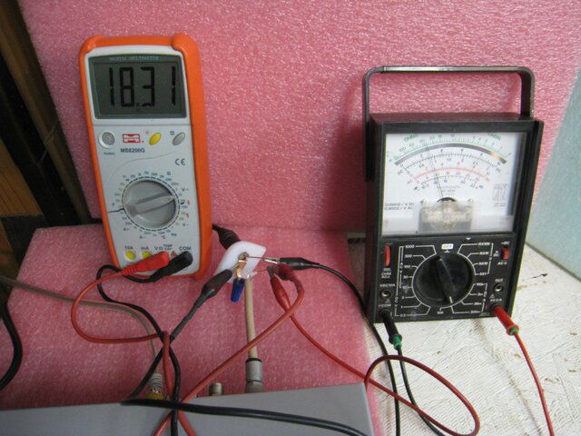
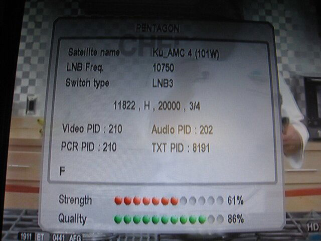
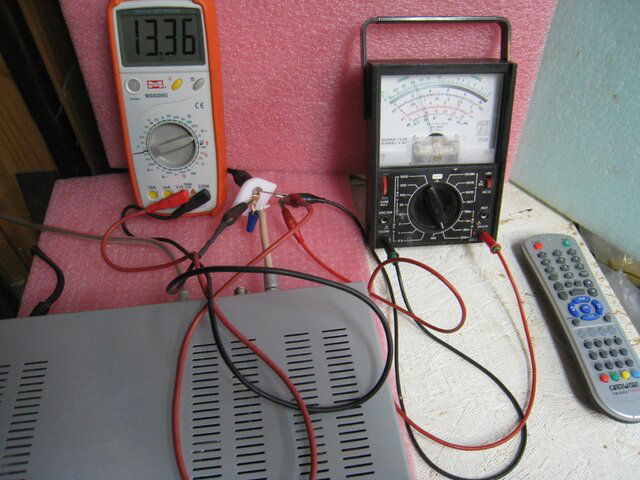
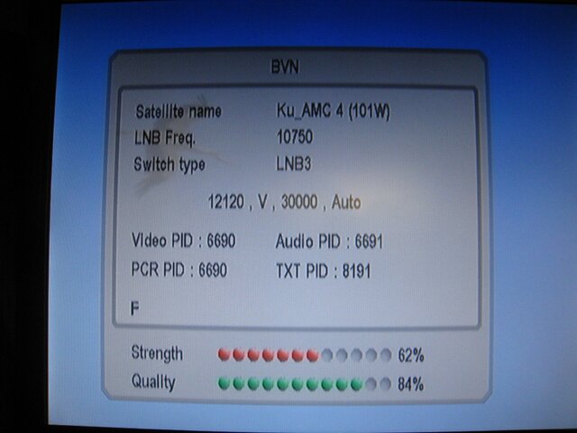
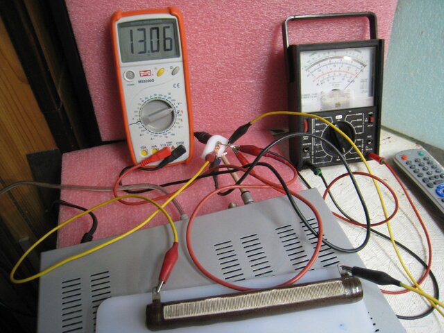
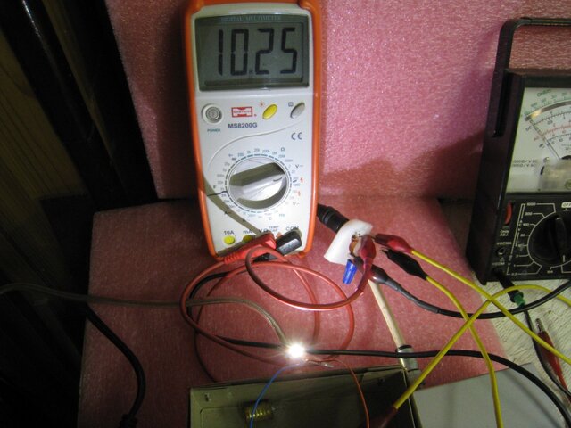
These cables from ampmeter and voltmeter did not influence the strength nor quality of reception. In this case, the LNB used only 85 mA. When I added a 50 Ohm resistor,( parallel to LNB) the voltage dropped slightly (as the current increased to 0.3 A). I tried to use small flashlight bulb in series, 2.2 V / 0.3 A, but it didn't even light... Then I tried an automotive LED diode (3 V, up to 0.1 A ) and the sat reception was still OK, despite voltage only above 10 V. Pictures follow
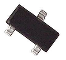
It was a Thermistor that Pixl found and fixed the problem. Read all about it here>RT, that sounds like a surface mount schottky diode, switching diode or even a transistor, since it has 3 legs. See image below (schottky diode). How did you make out?
http://www.satelliteguys.us/thread279413.html
.
RT.
- Status
- Please reply by conversation.
Similar threads
- Replies
- 4
- Views
- 588
- Replies
- 4
- Views
- 1K
- Replies
- 24
- Views
- 2K
- Replies
- 8
- Views
- 611


