Birdview reed sensor kit

Status
Please reply by conversation.
If I recall correctly, we thought the Gbox would do 4000 total, and the Vbox 2 would do 2000 total.
(Gbox = plus or minus 2000; Vbox = plus or minus 1000)
Problem is, the Gbox appeared to count on the contact closure and the contact opening of your reed switch.
(based on my understanding of the fine work Linuxman did)

So, while the Gbox certainly gave you twice as many reliable places to stop your dish, and that does increase accuracy, you still have a limited count-range that is essentially the same for both boxes.
That's why I was suggesting the lower count rate from your AMTencoder.

Now ... you know the number of turns the mechanism makes.
You know from the tables I presented above how many counts per turn the AMT can offer.
And you know the total count of Vbox=2000 or Gbox=4000, but with a caveat.

You should be able to select a count rate PPR (pulses per revolution) that'll maximize your counts without overflowing either box.
Also, in real life, you won't be running the mechanism from end to end, so if you'll read Linuxman's threads referenced above, you'll see how many counts he gets between his East and West limits.

Recap:

#1. I would certainly entertain the AMT.
It apparently has great potential.
You need to decide if it'll fit in the available space within the motor housing, up against the gears.

#2. The magnetic disc (I'd glue it on) is a winner.
From Linuxman's comments he seems to have a very strong 24-pole magnetic wheel and a reed switch.
I'm surprised this can work, but apparently it does.
His friend is right: looks like $20 worth of parts.
You would have to rig a way to mount the reed and keep it stationary, but I don't see that being a major problem.
Maybe the one you bought would work, if you got the strongest of magnetic discs... :confused:

#3. Personally, I'd look at using a hall-effect chip reclaimed from a dead PC-fan motor.
They are free, in unlimited supply (if I haven't thrown out all my dead fans), small, and low power.
The trick again would be mounting it, but I can see sticking it to a popsicle stick, and then flowing some epoxy overcoat onto it! :cool:
This would be a little less robust than a reed switch, but would last forever (if you didn't mess up your wiring).

#4. Having worked on projects with optical sensors before, I have a bad taste in my mouth from them.
I can envision all sorts of long-term failure modes (mostly concerned with small insects and dust).
Of course, those projects were a lot more touchy than just a simple on/off reading from a hole/slot in an opaque disc. ;)
So, I'm not totally against perusing that line of thinking... but I think any of the ideas above would be preferable.
 
Haven't made any progress yet

Hey guys, unfortunately I have not made any progress on this project as of yet. I did receive the reed switch that I posted about in #8 of this thread, but it looks like it is going to require a pretty strong magnet to activate it.

I did find a source of small neodymium magnets here, but I have not ordered anything yet. Regarding the pre-made magnetic targets, I just can't put $30+ into a magnet wheel plus shipping unless I know it will work.

My current idea is to make some type of wheel out of plastic or something and attach it to the end of the main shaft where the little pinion was for the original 10-turn pot setup. I was looking at mounting the magnets around the circumference and placing the reed switch near them.

But it seems that life gets in the way and I am not able to find time to work on my hobbies.

-Bryan
 
Hey Brian,

Thanks for the update.

I am going to have to put something together real soon myself and wondered how you had gotten along.

So you didn't ever go after the AMT-102 switch?

I am thinking about just going that route because it might be the path of least resistance.
 
The main reason that I didn't go forward with the AMT solution is that I don't yet have a VBOX or GBOX to see if it would work. The reed switch was a solution that would be easy to test (with a test light, or DVM).

Anole raised some concern with the weather resistance of that device, and I can see his point after seeing all of the mud dauber nests in my Birdview mount.

I plan on making this work, but it appears that I will be following your lead. I just don't have all of the equipment to put this whole thing together. I still need a receiver, a VBOX (or GBOX), an LNB, and the 300' of cable to get the dish to see clear sky. Heck, I don't even have a pole in the ground yet!

That being said, the AMT encoder is still my #1 choice when I get to that point. It looks like the closest thing to a plug-and-play solution. I am willing to set aside my concerns about the harsh environment that it would be in for the sake of simplicity. So go ahead and order one up and let us know how it works!!!
 
I plan on making this work, but it appears that I will be following your lead. .......So go ahead and order one up and let us know how it works!!!
:haha:haha:rolleyes:
I will have my neighbor come over this weekend and see what he thinks, and then make a decision.

It sure looks tempting, and would be pretty simple to implement, but I'll wait for another few days.
 
The optical sensor is a solution used in many common electronic devices. Most of the newer inkjet printers have an encoder wheel or encoder strip that an optic sensor passes that counts with very fine resolution. The problem with the optic metod is that dirt will be a problem. Gluing a disc with magnets fixed to the disc that passes a reed sensor or a hall sensor should be the ideal solution, as dirt should not be a big factor. Here is a little project to demonstrate the use of the hall effect sensor and should be easily converted for use in your project.
How It Works: Hall Effect Motor
A reed switch (found in the door sensor of alarm systems) is even simpler. Using either method, I think one should first build a test setup (i.e. without the actuator arm) to experiment with the strength of the magnets, placement of the magnets and placement of the sensor device, then once proven build a version for use on the actuator arm.

P.S. I do not plan on making one of the sensors, just found following the thread interesting and thought I would add my $0.02.....
 
That's pretty cool!

I don't mind exploring for a little bit. I have 12 magnets left over from another test I made. I can pick up 12 more for a couple of bucks. I'll see what I can find for a plastic disc. Thursday I'll be driving right by Gateway electronics. I'll stop in and see what they have in the way of a reed switch.

I just need to figure out how to lay the magnets out on the disc. All facing one way or alternating?
 
Alright, I went shopping today for parts to start making the sensor and wheel.

I stopped by Gateway Electronics but they didn't have any magnet wheels. I asked the guy for ideas, but he wouldn't even give any hints. He said bring a parts list and he would give me what I had on the list.

Stopped by an old hardware store that has been there for decades and asked the guy for ideas. Fortunately I had one of the spare motors with me. :)

He took me right to the shelf where they had the locking collars and a 1/2" fender washer which was 2" diameter. I also bought a bottle of contact cement.

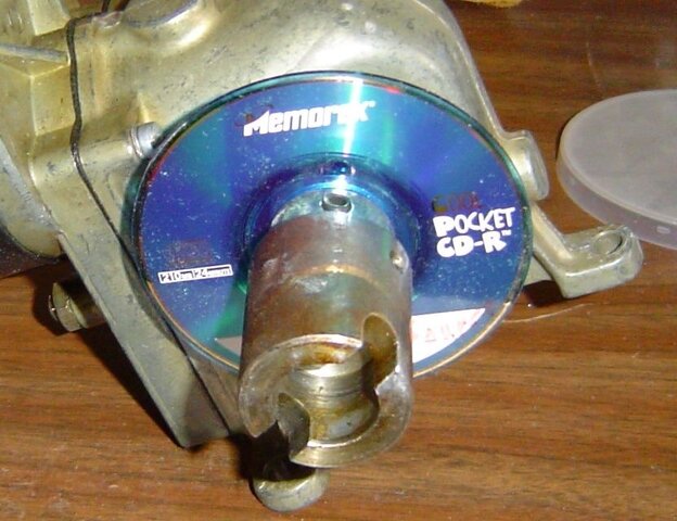
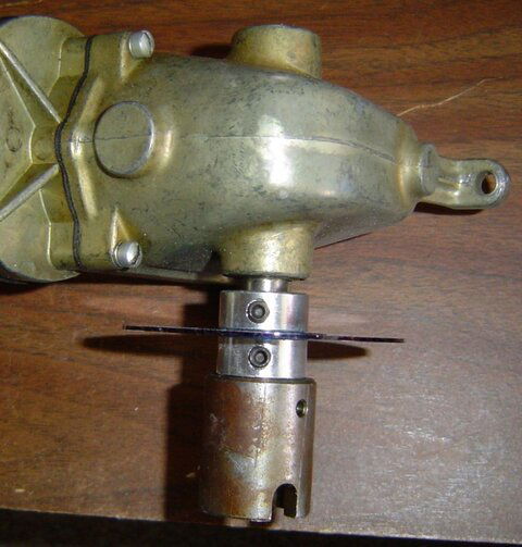
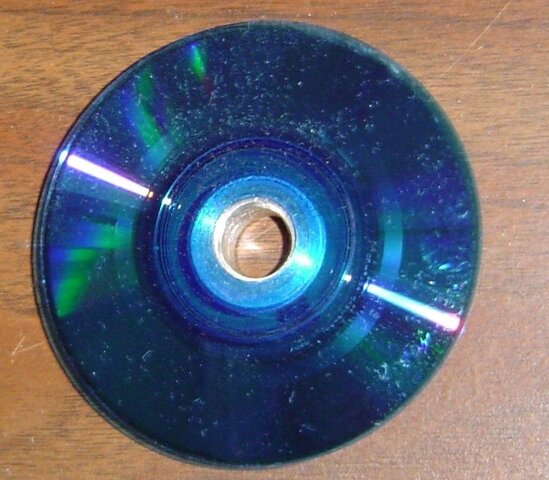
Got home and the washer was just too small. Looked around for something 3" diameter which is about what is needed. I found this old pocket CD-R which is exactly 3" diameter. It is rigid, can glue magnets to it, or carefully grind notches in it if we go the light route.

So far, I've got $6.63 including tax tied up in this project and $3.79 of that was for the glue. :eek:

I am working from the motor end of the shaft because that is where the original was attached, and I think it will be easier to make a holder using the bolts on that end.

The shaft is 1/2" diameter so standard parts work. You can see below the center hole of the CD is just slightly larger than 1/2" so it will have to be cemented in place to be balanced.

Three inches is about the size of the magnet wheel from the conversion kit. Don't have an exact figure without taking the hood off my existing Birdview and measuring it. I think it is pretty close.

Here are the pics:

sensor-disc.jpg sensor-disc-top.jpg sensor-disc-center.jpg

To glue 24 magnets to this disc, they would need to be spaced at .4" (I found an online calculator to get the circumference) :) apart on centers at the outside edge. Close but do-able. I have a package of 1/2" magnets here, but they are too big I think. A package of 12 is only a couple of bucks at the Hobby Lobby.

So what do you guys think?

Am I on the right track?
 
I think you're doing Great! I just got my Kit out again, actually I haven't put it back up yet. I measured across the Disk and it's 3-1/4" across, it's 5/16" thick. It looks a lot like a Grinding Disk? You might consider using a Grinding Disk, I'm sure you can find one close to the right size?
What kind of Glue are you using? I've taken an old Venture Actuator apart and found one of the housing Magnets loose. I'm thinking it may be what was locking it up? What is the right type of Glue to use to hold this Magnet in place? Maybe I can get the Venture to work?
 
I measured across the Disk and it's 3-1/4" across, it's 5/16" thick.
Thanks Al! Thanks for the precise information. I appreciate it a bunch!!

I just went out and looked at the mount on the porch, and there isn't much more room for anything bigger than 3" to 3-1/4" dia disc. The 5/16 thickness is because of the embedded magnets. Once there are magnets on this disc, it will be a similar thickness.
It looks a lot like a Grinding Disk? You might consider using a Grinding Disk, I'm sure you can find one close to the right size?
I thought about a grinding or sanding disc but couldn't find one today that fit the bill. The mini-cd may not work, but it is close to the right size and already cut. :)

What kind of Glue are you using?
I bought what the guy recommended. Just plain old contact cement. It will glue about any substance to any other kind of material and doesn't require clamps to hold it together. Almost instant adhesion.

Hope that helps you out. Thanks for the measurements!
 
Hey Larry,

Thanks for the links.

It looks like I will have to use 1/4" magnets as they are going to be spaced approx. 3/8" apart at the center if I am going to get 24 on the disc. They need a little space between each magnet for the switch to do it's thing.

If I can't find any locally here tomorrow, I will order from this company provided that's the way I end up going.

I need to check with my neighbor to get his input. :)
 
You should be able to get simular magnets from a woodworking/cabinet making supply shop in your area.
I guess you are right, I never thought about a cabinet shop until I just put the 2 pieces of the puzzle together. The website is a woodworking sales site. :)

Well my neighbor came over tonight and said the following:

The simple and easiest approach is to duplicate the current kit as closely as possible.

He liked my idea of the mini-cd disc. Cheap and available for experimentation.

He said to try and find the 1/4" magnets, if not there is a way to make 1/2" magnets work with two switches off-set from each other and use 12 magnets and still get 24 pulses. I didn't understand that part, but I do trust him.

He said to try and buy things that are readily available from Grainger or Digi-Key so we can get them again when needed to duplicate the kit.

He also said the contact cement was fine for the proto-type, but epoxy would be better for being out in the heat and cold.

The light emitter is a good idea and we could pursue it, but understood the point made here about critters interfering with the light source.

He said there were a hundred different ways to do this, but keeping it simple and working was the best way to go, and the least expensive.

So I am going shopping again tomorrow to get magnets, mini-cds, epoxy, and a couple of reed switches.

I hope to have something working by Sunday evening. :)
 
They need a little space between each magnet for the switch to do it's thing.

Thats where
"I think one should first build a test setup (i.e. without the actuator arm) to experiment with the strength of the magnets, placement of the magnets and placement of the sensor device, then once proven build a version for use on the actuator arm."
 
Thats where
"I think one should first build a test setup (i.e. without the actuator arm) to experiment with the strength of the magnets, placement of the magnets and placement of the sensor device, then once proven build a version for use on the actuator arm."
That's precisely what I am going to do with this extra motor. :)
 
Status
Please reply by conversation.

Norsat 8530i lnb

Remote Control 650i

Users Who Are Viewing This Thread (Total: 0, Members: 0, Guests: 0)

Who Read This Thread (Total Members: 1)