AMIKO Amiko A3 Owners Thread
- Thread starter KE4EST
- Start date
- Latest activity Latest activity:
- Replies 895
- Views 138K
You are using an out of date browser. It may not display this or other websites correctly.
You should upgrade or use an alternative browser.
You should upgrade or use an alternative browser.
Well then there is the question, could it simply be that the A3 is defective?
I'm going to connect my Turbo S2 meter in the middle and see what it has to say about the output of the two STBs. There is an option that reads the voltage output of the STB.
It won't read the Discque commands though. THAT would be excellent, to have a meter that actually reads the commands being sent down the wire and reports them to you.
Well then there is the question, could it simply be that the A3 is defective?
Yes, that of course could be possible, but of course the only real test for that is exchanging for another A3. I've been reading all the threads between here and the fridge, and I don't remember reading anybody else with this issue. There are a few others that did a complete reset like you did though, so you aren't the only one. I don't think you were the first either.
Unless Brian has some other ideas to try.
My meter has a sort of a spy on the wire feature.
It shows me the voltage the STB is outputting and it shows the voltage and I guess amperage the LNBF/motor is drawing.
When it moves to a satellite that was last tuned to a horizontal channel, it draws 17.x volts and the amperage will run up as high as 700mA !! That's what the motor is pulling.
Obviously the MicroHD is supplying it without any problem at all. The A3, not so much.
I recorded a video of me moving the dish around with the MicroHD and it shows how it jumps up and down and all around.
I'm going to post the video to youtube and link it here in a short bit.
Next I'm going to remove the MicroHD and put the A3 in it's place and record the meter readings from it and post them separately.
This motor is drawing a heavy load and apparently the A3 can not provide what it needs. This would explain my problems.
The motor and the LNBF combined current draw will likely exceed the A3 current rating. If the A3 is not displaying an over-current warning, then it is probably not a current related issue. Does the motor reliably move with the A3 if the USALS commands are issued on a Horizontal polarity transponder (channel)?
It would be informative to know if the motor LED blinks while the A3 USALS commands are issued. This would likely be related to 22KHz/DiSEqC amplitude. If this the case, passing through the ASC1 will amplify the control signals and provide proper voltages and higher current availability for your KU HH motor
It would be informative to know if the motor LED blinks while the A3 USALS commands are issued. This would likely be related to 22KHz/DiSEqC amplitude. If this the case, passing through the ASC1 will amplify the control signals and provide proper voltages and higher current availability for your KU HH motor
The motor and the LNBF combined current draw will likely exceed the A3 current rating. If the A3 is not displaying an over-current warning, then it is probably not a current related issue. Does the motor reliably move with the A3 if the USALS commands are issued on a Horizontal polarity transponder (channel)?
It would be informative to know if the motor LED blinks while the A3 USALS commands are issued. This would likely be related to 22KHz/DiSEqC amplitude. If this the case, passing through the ASC1 will amplify the control signals and provide proper voltages and higher current availability for your KU HH motor
You know, this is very interesting because when I passed everything through my Turbo S2 meter, the dish moved just fine. I was shocked to see it work as it should.
I moved it back and forth between different satellites and different polarities and I recorded all the various readings I got from both the MicroHD and the A3.
I'm running them through handbrake now so I can upload them to Youtube. I imagine it's going to take some time to upload and process.
I'm making the videos "unlisted" on there but I'll list them here. I just don't want all the riffraff of youtube on there trolling for trouble.
I can't really do anything about the led on the motor now because it is raining and lightning. As soon as it stops, I'll prop my iPhone up where it can see and record the motor LED then I'll come in the house and operate the motor.
I'll do it with the meter inline and with the meter not inline so we can see if my meter is providing a boost to the process or not.
That will likely be tomorrow before I can do anything about the LED lights. There's just no way to go out there tonight and mess with it.
The videos of the meter readings showing the voltages and stuff is uploading now. I'll post links here when they are ready.
IF my meter provided a boost to make it work right, then there's a chance having the ASC1 inline will do the same, yes?
The ASC1 actually is designed to output 22KHz/DiSEqC at a considerably higher amplitude.
I'm not sure exactly what that means but I take it that it's a good thing.
I'm assuming that it means it will add to or boost the power coming from the A3 going to the USALS motor.
This is a video of the meter giving readings while the MicroHD is moving the dish around between 87, 97 and 125.
I made it change channels to transponders to show the voltage change between H and V.
I also had it move the dish between sats that had last tuned to different polarities to show the difference in draw as it operates the motor on 13v and 18v.
So I pretty much put it through it's paces here. Pretty boring stuff so skipping around is probably your best best.
I'll paste the link for the readings from the A3 as soon as they are available.
And here it is, the readings I got from the A3..
Last edited:
If you're connecting the meter inline between the motor and the A3, then maybe the center connector of the coax that was hooked to the A3 is a bit short and not making a good connection, but when you connect the meter up, whatever short piece of coax you're using to go to the A3 is making a good connection? You could swap the meter with one of these if you have one laying around, just to check.

The motor movement doesn't seem to increase the current draw. This makes no sense. The high current draw on horizontal polarity is also very unusual.
What is downstream from the motor? Switches? LNBFs? Brands? models?
I wouldn't expect to see 290mA Vertical / 490mA Horizontal draw by a KU LNBF.
What is downstream from the motor? Switches? LNBFs? Brands? models?
I wouldn't expect to see 290mA Vertical / 490mA Horizontal draw by a KU LNBF.
In each of the videos there is an ohms read out just below the current draw numbers.
What does the ohms reading represent?
That ohms readings fluctuate from a low of 26 up to 43.
Also the current draw increases as the ohms go down and current draw decreases as the ohms go up.
Can the A3 rated at 400ma sustain a continuous load of 500ma+ for any length of time?
What does the ohms reading represent?
That ohms readings fluctuate from a low of 26 up to 43.
Also the current draw increases as the ohms go down and current draw decreases as the ohms go up.
Can the A3 rated at 400ma sustain a continuous load of 500ma+ for any length of time?
Ok, to be exact, the things that are down the wire AFTER the motor are a 22k Ecoda which is defaults to off for the KU.
I have a 3x4 switch combining the output of the old school H V output LNBF.

I did a little crude artwork that's a fairly close approximation of the way things are connected.
It's actually a little more complicated than that because wires run back and forth from the dish to the waterproof box a few times and I have all the wires tied together in bundles so it's hard as heck to figure out which on goes where.
In a week or so I'm going to rip the entire yard and system completely apart. Wallyhts is selling me one of those "Texas size DiSEqC enclosures" http://www.satelliteguys.us/xen/threads/texas-size-diseqc-enclosure.340209/ and I'm digging up the PVC pipes the wires are buried in and putting in 4 inch PVC pipes and a few spare wires while I'm at it.
EVERYTHING comes apart and everything is being redone from scratch. I'm going to have the pipe come out of the ground and into the enclosure where and that is being placed where I have easy access to it.
Right now I have those old toolboxes and they are in a very awkward spot.

When I have everything apart I'm going to use my wire tester to locate every single wire and label every single wire so I know what the h*ll is what and where it goes.

It makes me insane trying to figure out wires when they are all tied into bundles. Those days are coming to an end soon.
I'm also going to put a WIFI in that box so I can operate stuff from out there.
Anyway, back on subject. I did not know or think that anything AFTER the motor would be a problem.
I can't really eliminate the 3x4 switch, it needs to stay. I don't know how I can eliminate the 22k switch, I assumed it was the best solution to have the C-band and KU on a single wire.
I've had poor luck using assorted DiSEqC switches in it's place. I figured with the Ecoda if I put the KU motor on the zero side of the switch that the switch wouldn't account for anything, it would just pass through it invisibly, without penalizing the signal, right?
I have a 3x4 switch combining the output of the old school H V output LNBF.
I did a little crude artwork that's a fairly close approximation of the way things are connected.
It's actually a little more complicated than that because wires run back and forth from the dish to the waterproof box a few times and I have all the wires tied together in bundles so it's hard as heck to figure out which on goes where.
In a week or so I'm going to rip the entire yard and system completely apart. Wallyhts is selling me one of those "Texas size DiSEqC enclosures" http://www.satelliteguys.us/xen/threads/texas-size-diseqc-enclosure.340209/ and I'm digging up the PVC pipes the wires are buried in and putting in 4 inch PVC pipes and a few spare wires while I'm at it.
EVERYTHING comes apart and everything is being redone from scratch. I'm going to have the pipe come out of the ground and into the enclosure where and that is being placed where I have easy access to it.
Right now I have those old toolboxes and they are in a very awkward spot.
When I have everything apart I'm going to use my wire tester to locate every single wire and label every single wire so I know what the h*ll is what and where it goes.

It makes me insane trying to figure out wires when they are all tied into bundles. Those days are coming to an end soon.
I'm also going to put a WIFI in that box so I can operate stuff from out there.
Anyway, back on subject. I did not know or think that anything AFTER the motor would be a problem.
I can't really eliminate the 3x4 switch, it needs to stay. I don't know how I can eliminate the 22k switch, I assumed it was the best solution to have the C-band and KU on a single wire.
I've had poor luck using assorted DiSEqC switches in it's place. I figured with the Ecoda if I put the KU motor on the zero side of the switch that the switch wouldn't account for anything, it would just pass through it invisibly, without penalizing the signal, right?
If you're connecting the meter inline between the motor and the A3, then maybe the center connector of the coax that was hooked to the A3 is a bit short and not making a good connection, but when you connect the meter up, whatever short piece of coax you're using to go to the A3 is making a good connection? You could swap the meter with one of these if you have one laying around, just to check.

That was a problem I learned early on in my (never ending) learning days. So when I make connections I always make the copper center wire a little longer than normal.
Through trial and error I found out how much was too much where I would have to trim it down. I am consistent with my connections now.
I am also very careful to take the time to very thoroughly clean any stray little strands from potentially shorting out from ground to the center conductor as well as the foil.
Before I put the fitting on I inspect the wire with my super strong glasses so I can see any flaws/errors and correct them OR, in some cases, just clip it completely off and start over before I waste a new connector.
As for the inline connectors, that's pretty much what I have. Only I got mine from the TW cable. After a hurricane I drove around and saw hundreds of wadded up piles of cable tv wires at the curb in front of everyone's home, they got pulled down by limbs so the cable guys would just rip the old wires down, run new wires and throw the old stuff to the curb. I picked up a bunch of it thinking I could reuse it for satellite.
Eh, it was pretty old, low quality wire but I got all sorts of cool connectors and doo-dads out of the deal. So I stripped off the doo-dads and threw the wires away.
Those old cable tv barrels might NOT be 3Ghz rated, and that can cause signal problems and notch-outs. They might not be causing your specific problem, but I'd replace them (actually I'd eliminate them if possible) with ones rated 3Ghz for sure.
I understand. I just assumed they were nothing more than a copper bridge. Apparently not. I will shop for quality replacements.
I actually don't use them much, there was one to splice the wire coming through the wall from the KU dish to make it longer so it could run through the wall into my bedroom where the MicroHD was (and will return to).
I am not using that in this situation, I removed it and connect the wire directly into the A3 (or my meter). When I was using it for the MicroHD I never had any known issues. Everything worked as it would be expected to work.
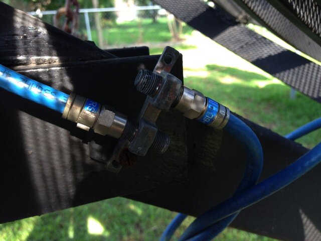
I do have one on my C-band dish. I found out the hard way that you just can not have an unbroken run from the LNBF to the STB. You have to have a way to disconnect to put a meter inline, for obvious reasons.
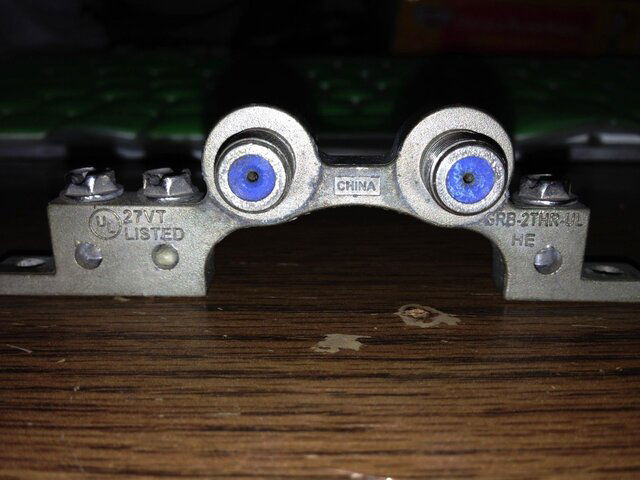
So I put a dual splice thingie at the dish and I have three outputs (a 3x4 switch again) one goes to the other side of the Ecoda (previously mentioned) another goes to a second wire to feed a second system (does not pass through the splice) and a third wire is available under the dish to put my meter on without disconnecting anything else.

This is from a few months ago when I connected it up wrong after fiddling with things.
I was befuddled as to why I couldn't get a signal in the house. Until I discovered this. Oops.
Those are the only two splice thingies I have in actual use. I have several of them in junk boxes, sometimes I will use one when I'm working on something and I need to make a wire longer so I can walk around with my meter.
I honestly never thought that there was a rating on them other than "Chinese grade" and "not Chinese grade"..
And in a few days THAT issue will not be an issue any longer..
Usually the Blue inner insulator on the barrel connector is the 3GHZ identifier or satellite rated. Thats the kind I use (as few as possible).
Uh oh..... Did I just make a mistake?
Here's the text from the description of the connectors I bought.
Auction its for "10 pcs" of Directv approved F-81 HF 3GHz Barrel Connector,line Splice with weather seal.lot of 10 pcs
manufacturing: Perfectvision
High Frequency Barrel Connector
In-line Splice Connector for High Frequencies
?Internal components designed for high frequency
?Gold plated center conductor assures minimum RF loss & good electrical connections
?Resilient internal metals for dependable repeated insertion connections
?Included weather seals on each side
?Minimal insertion loss ds\specifications\dtvf81o-05
Product Description
Rated for 0 MHz through 3 GHz
The internal components of this fitting are much different from a standard VHF/UHF barrel connector. The center coax conductor indexes into a close-tolerance tube that is resilient (spring) brass and is gold plated.
The close center-tube tolerance assures a tight connection, the gold plating assures a good electrical connection and the overall performance is greatly improved over standard designs.
Internally, the center conductor tube is insulated from the inner skin of the barrel by a maximum air gap which results in much less RF loss. Insertion loss is extremely low and not really necessary to consider in complex systems.
Intended for outdoor use. Rubber weather seals on each side provide an added layer of moisture resistance.
edit: Found one with blue insides in my junk box.

Last edited:
Similar threads
- Replies
- 1
- Views
- 343
- Replies
- 0
- Views
- 300
- Replies
- 5
- Views
- 469
- Replies
- 2
- Views
- 704
- Replies
- 7
- Views
- 1K


