Smallest EMWIN antenna

Status
Please reply by conversation.
Thanks :) so instead of an expensive hackrf, bladerf or usrp, you are thinking of rolling your own board?

I haven't found any sdrs that do what I want. The hackrf, bladerf or usrp seem a bit overkill(And expensive) for me and the prototype board on the goes website uses a lot of obsolete parts. My current design still looks like it will cost approximately $150-$200 for a one-off board. Since I am doing this mostly for the challenge I'm not figuring in programming and design time! (Although the price should drop considerably if I would do 20 or more at a time)
 
I really like that idea! Especially if it will help others to cheaply receive the data. Would it perhaps be any cheaper to print the ocb at home using a laser printer transfer method and etch it / drill the via holes? I know it will be hard to work around component costs.
 
For 1 PCB it would probably be cheaper doing it yourself although I'm not sure if we would need more than one layer(and everything will be surface mount so it will be really tiny). For more than 50 some places it's as cheap as $4-$7 a board, not a bad price. Also I think the FPGA I have in my plans is over kill to, I don't know how many gate,ram and LABs I need to do BPSK demodulation(Costas tracking, viterbi whaterver is needed). The reason I would like if the FPGA could do most of the processing is that you could use a raspberry pi as the display.
 
Thank for the Max2021 evaluation kit info, one would still have to build the USB interface. I am working on a new schematic (With Ki-cad, on Linux(of course)) as soon as I get a decent scketch I'll post it.
 
The max2120 has 75ohm impedance and the antenna 50ohm. Should I include a 50ohm-75ohm balun or ignore the mismatch, which would create the greatest loss?
 
I think the antenna on your dish and mine (TP-LINK TL-ANT2424B) is a 50 ohm dipole w/ 50 ohm N connectors. Not sure what type of coax we are each planning on using or how long of a run will be supported but if the unit were located outdoors with the dish in a weatherproof enclosure, wouldn't that make impedance matching easy peasy (50 ohm) hooked straight to the antenna and not lots of coax in the system to create loss? - thing here is I don't know whats out there in terms of usb isolation / surge suppression - i know there are usb repeaters (long usb cable running out to antenna / receive system type scenario).

As far as the antenna / IC impedance mismatch goes, There's got to be some kind of calculators out there to see what would have the least loss.
Not sure if it is possible for us to rewire our dipoles for 75ohm impedance. (don't even know if that would be a good idea)
 
Perhaps if the 50 ohm antenna connection was brought in, hooked to an LNA (signal amped up = more to work wirh?) then put through a balun or some sort of impedance match procedure then brought into the tuner chip at 50 ohm, perhaps this setup might work? not sure if this is hacky or not though.

That was theoretically the little bit of loss encountered by matching wouldn't matter.

something i'm reading http://www.bluejeanscable.com/articles/impedance.htm
 
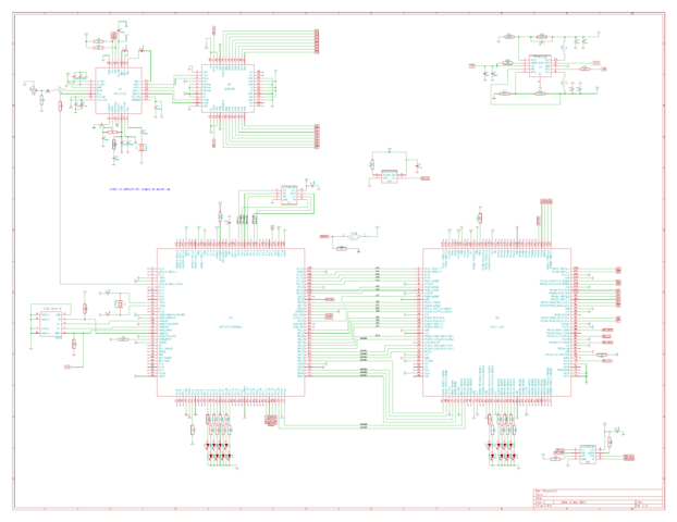
Just an update of my current schematic.
upload_2014-8-19_19-1-58.png
 
Ok. I'm back! Here is my "finished" schematic for my 1-2 ghz sdr. Please point out any thing missing/stupid/that won't work in my design.

Here is a simple block diagram of the process.
Note: The micro controller will be able to program the fpga boot flash.
block.png


Emwin.png
 

Attachments

Just an update.
  1. Corrected current limiting resistor sizes for debugging leds.
  2. adjusted DC blocking cap for 1.69 GHz RF input
  3. small typos.
 

Attachments

This is aaaaawesome!
What is it going to take to get some prototype pcb's out of this schematic?

I think we should post this in some of the SDR groups such as ultra cheap sdr to hopefully solicit feedback from folks who really know their stuff! - I'm also really hoping that some very knowledgeable RF members from here on satguys will chime in.

What kind of driver or software is going to need to be running on the host OS?

https://groups.google.com/forum/#!forum/ultra-cheap-sdr

I don't see anything obviously bad going on here - but then I'm not a RF engineer either.
I do have a close friend who worked for a NASA contractor who knows alot more about the inner workings of stuff RF wise. I shall show this tread to him.
 
"What is it going to take to get some prototype pcb's out of this schematic?"
I am working on creating footprint drawings for kiCad, then I will make a board layout. I might use https://oshpark.com/
"What kind of driver or software is going to need to be running on the host OS?"
I will probably first write a driver for SDR# or linrad. Then make Emwin/LRIT/HRIT display software.

Here is my current parts list (http://www.digikey.com/short/7cbbvv)

Any suggestions? I look forward to hearing from your friend.
 
Status
Please reply by conversation.

Users Who Are Viewing This Thread (Total: 0, Members: 0, Guests: 0)

Who Read This Thread (Total Members: 2)

Latest posts

Top