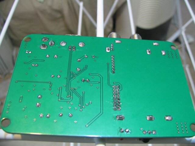
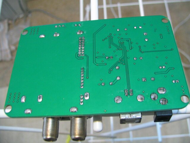
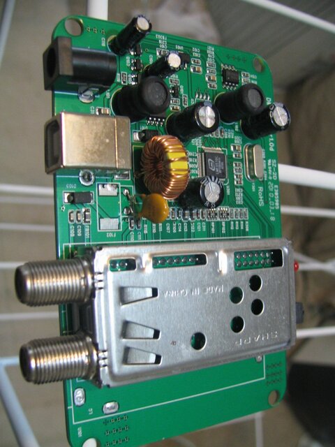
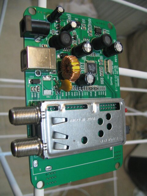
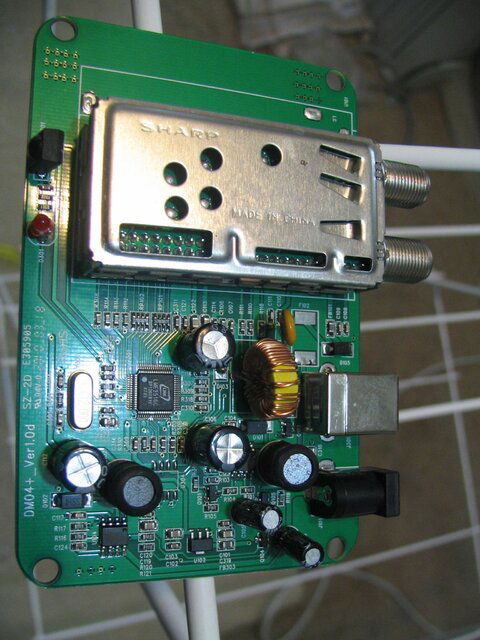
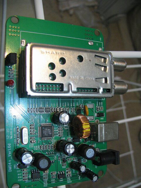
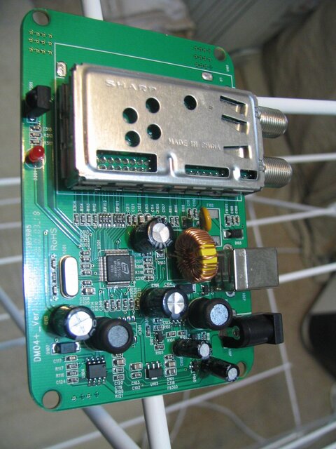
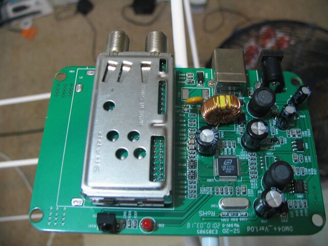
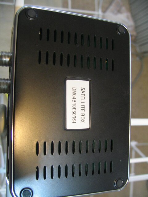
QQ BOX MOD PICS.
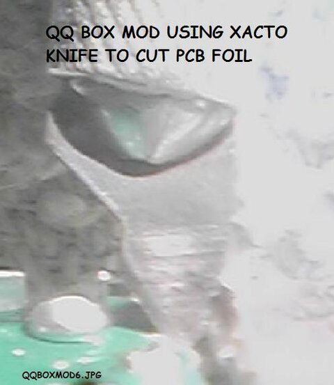
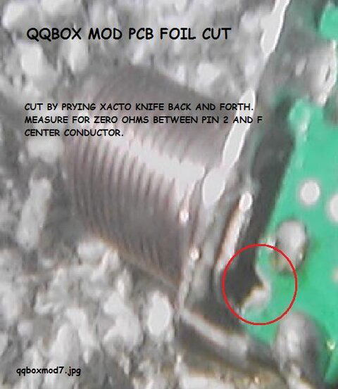
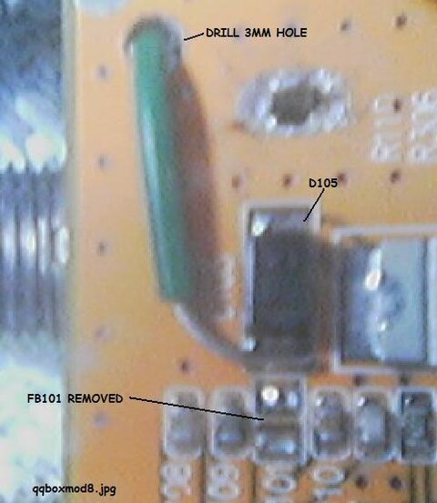
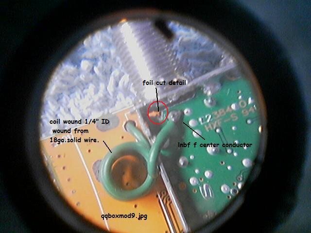
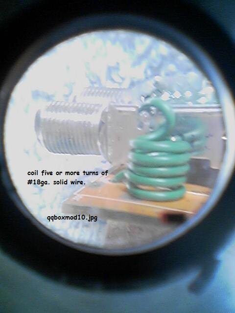
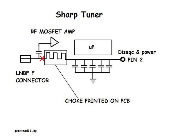
Yes there is a decoupling cap. it is part of rf amp input. blocks the dc voltage. The F center conductor takes two paths, one to pin 2 and off to FB101 and another path through cap to Mosfet. The current carry capacity out to the h-h motor is improved by this mod due to the #18ga. wire. The pcb has an ultra thin trace and would be high resistance at 300ma. See qqboxmod1.jpg for the decoupling cap. it is just to the upper right of the cut foil trace.
DO NOT ATTEMPT THIS MOD UNLESS YOU REALLY KNOW WHAT YOUR DOING OR YOU WILL FOR SURE RUIN THE QQ BOX.
some more pics.
In your version of the mod, you do not have a decoupling capacitor, and the DC is still traveling inside the tuner. I haven't tried it yet and i don't have information whether it is good or bad. However, because of the high frequencies, generally it is not a good idea to mess with the tuner internals. Can you provide a better photo of the opened tuner? I haven't desoldered mine, and I want to see if I can figure out what is wrong with the layout.
10x in advance
Yes there is a decoupling cap. it is part of rf amp input. blocks the dc voltage. The F center conductor takes two paths, one to pin 2 and off to FB101 and another path through cap to Mosfet. The current carry capacity out to the h-h motor is improved by this mod due to the #18ga. wire. The pcb has an ultra thin trace and would be high resistance at 300ma. See qqboxmod1.jpg for the decoupling cap. it is just to the upper right of the cut foil trace.
DO NOT ATTEMPT THIS MOD UNLESS YOU REALLY KNOW WHAT YOUR DOING OR YOU WILL FOR SURE RUIN THE QQ BOX.
some more pics.
Attachments
Last edited:


