QQ-Box USB DVB-S Tuner - Unknown Device?
- Thread starter 1ADAM12
- Start date
- Latest activity Latest activity:
- Replies 381
- Views 178K
You are using an out of date browser. It may not display this or other websites correctly.
You should upgrade or use an alternative browser.
You should upgrade or use an alternative browser.
- Status
- Please reply by conversation.
DM04/QQbox DiSeqC output - the hard truth.
The problem has been resolved. I will release the driver fix soon.
Still can't figure out how to drive the rotor to goto 0. I will try to do it with Myth TV tomorrow.
1ADAM12-
Unfortunately, there is no script to install v4l. I will see, if I can make one when I have the time.
nook-
get your box replaced, you could damage your LNB.
QQ Box Diseqc Fix
Thanks M.
The problem has been resolved. I will release the driver fix soon.
Thanks M.
The problem has been resolved. I will release the driver fix soon.
Driver fix to add Diseqc functionality to the QQbox?
Driver fix to add Diseqc functionality to the QQbox?
His Linux driver will do Diseqc 1.0 / 2.0 and 1.2 to drive an H-H motor. It already works with Diseqc switches using factory driver.
I have updated my driver, but the QQBox is still troublesome. However, the DM04 works fine.
The QQBox appears to suffer a design issue, with the LNB voltage which appears to have a great deal of switching noise coming from the DC-DC converter close to the tuner. This may trigger the LNB to the high band and disrupt DiSeqC commands. However, if QQBox sends command under windows to a switch it should be okay.
The layout of DM04 is different in that the DC-DC converter is well away from the tuner.
I have updated my driver, but the QQBox is still troublesome. However, the DM04 works fine.
The QQBox appears to suffer a design issue, with the LNB voltage which appears to have a great deal of switching noise coming from the DC-DC converter close to the tuner. This may trigger the LNB to the high band and disrupt DiSeqC commands. However, if QQBox sends command under windows to a switch it should be okay.
The layout of DM04 is different in that the DC-DC converter is well away from the tuner.
This issue was discussed and a fix was suggested by another member. A shielded coil was given as a fix for the switching power supply and a part number was given.
QQ Box L101 Fix
The Fix is to replace L101 torroid with a MuRata shielded coil. www.mouser.com has them instock for $0.85 @ no minimum order.
p/n
12RS224C
The Fix is to replace L101 torroid with a MuRata shielded coil. www.mouser.com has them instock for $0.85 @ no minimum order.
p/n
12RS224C
Attachments
Yes, I have ordered the part. This is the primary reason for DOA QQBoxes particularly with Windows where tuning starts in the low band.
However, I have managed to drive the rotor successfully on the end of a switch. Interestingly, the rotor gives more trouble being driven of LNB 1 than any other port.
The timing for DiSeqC commands is critical with the Linux STV0288 module. It needs some work done on it to bring it up to level 2.x. There is also no error checking. I am currently working on this.
L101,L102 &L103
Yes, this seems to be the reason for sporadic operation and better operation without the case. After reviewing the schematic, I'm inclined to replace all filter chokes with shielded inductors.
The comment that was made to me by the factory was; It is a problem with software and hardware, but that was not illuminating.
They may not really know what the problems are. I did go as far as giving them extensive documentation on Diseqc 1.2 implementation standards. But that died from their end.
Another issue I noticed with their driver; at times depending on lnb settings, the chopper is given 22Khz through the V/H switch and can burn up the L101 filter cap.
Yes, I have ordered the part. This is the primary reason for DOA QQBoxes particularly with Windows where tuning starts in the low band.
However, I have managed to drive the rotor successfully on the end of a switch. Interestingly, the rotor gives more trouble being driven of LNB 1 than any other port.
The timing for DiSeqC commands is critical with the Linux STV0288 module. It needs some work done on it to bring it up to level 2.x. There is also no error checking. I am currently working on this.
Yes, this seems to be the reason for sporadic operation and better operation without the case. After reviewing the schematic, I'm inclined to replace all filter chokes with shielded inductors.
The comment that was made to me by the factory was; It is a problem with software and hardware, but that was not illuminating.
They may not really know what the problems are. I did go as far as giving them extensive documentation on Diseqc 1.2 implementation standards. But that died from their end.
Another issue I noticed with their driver; at times depending on lnb settings, the chopper is given 22Khz through the V/H switch and can burn up the L101 filter cap.
Last edited:
signal/quality
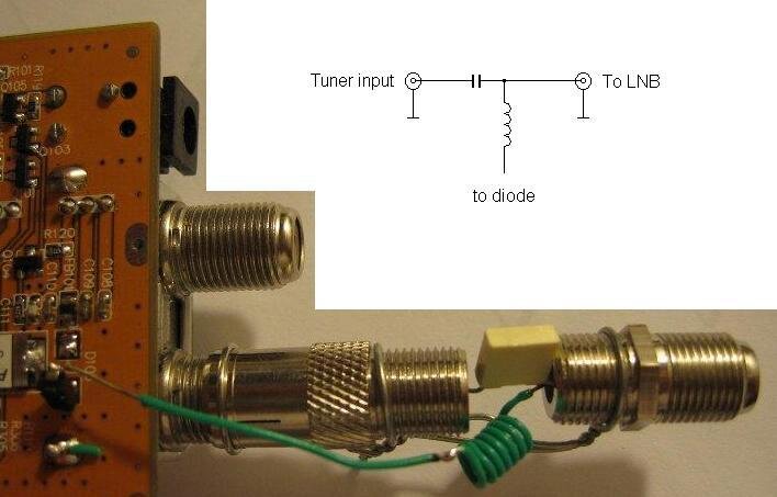
I've noticed a strange behavior of the QQ-box. There is great difference in signal/quality, when powering the LNB through the Sharp tuner, and powering it externally, using loop-out of my dreambox (using decoupling capacitor). On a transponder showing about 30% of quality (using windows driver), when powering the LNB externally I have 80-90% of quality! After i suspected a noisy DC/DC of the QQ-box, I've tried to power LNB bypassing the Sharp tuner. I desoldered the Schottky diode before the tuner and connected it externally through a RF decoupling coil and a decoupling capacitor to power the LNB. For my surprise the quality rose from about 30% to about 70%!
I've noticed a strange behavior of the QQ-box. There is great difference in signal/quality, when powering the LNB through the Sharp tuner, and powering it externally, using loop-out of my dreambox (using decoupling capacitor). On a transponder showing about 30% of quality (using windows driver), when powering the LNB externally I have 80-90% of quality! After i suspected a noisy DC/DC of the QQ-box, I've tried to power LNB bypassing the Sharp tuner. I desoldered the Schottky diode before the tuner and connected it externally through a RF decoupling coil and a decoupling capacitor to power the LNB. For my surprise the quality rose from about 30% to about 70%!
Schematic needed
This is interesting information.
Can you post a diagram of your modification?
I've noticed a strange behavior of the QQ-box. There is great difference in signal/quality, when powering the LNB through the Sharp tuner, and powering it externally, using loop-out of my dreambox (using decoupling capacitor). On a transponder showing about 30% of quality (using windows driver), when powering the LNB externally I have 80-90% of quality! After i suspected a noisy DC/DC of the QQ-box, I've tried to power LNB bypassing the Sharp tuner. I desoldered the Schottky diode before the tuner and connected it externally through a RF decoupling coil and a decoupling capacitor to power the LNB. For my surprise the quality rose from about 30% to about 70%!
This is interesting information.
Can you post a diagram of your modification?
New Fix
Nicely done!
Good documentation
If you were to put the coil in series with D105 and found no improvement then the tuner is part of the problem. If it worked better then without the coil then the RF hash from the chopper is being reduced.
The values of the capacitor and the inductor are not critical. In my case the capacitor is 220nF and the inductor have 7 turns with inner diameter of 3mm. I know that this is not the right way - it was just an experiment showing where the problem is.
Nicely done!
Good documentation
If you were to put the coil in series with D105 and found no improvement then the tuner is part of the problem. If it worked better then without the coil then the RF hash from the chopper is being reduced.
Last edited:
No Improvement
That is good information.
Even though the tuner is a "Sharp" product, it is made in China not Japan, quality suffers.
I noticed that without the case there are fewer problems, possibly the L101 hash getting into the tuner. Have you tried slipping the case over your modified board, leaving the end open?
If i put the coil in series with D105, there is no improvement. So I suspect a problem with the inner layout of the small sized Sharp tuner.
That is good information.
Even though the tuner is a "Sharp" product, it is made in China not Japan, quality suffers.
I noticed that without the case there are fewer problems, possibly the L101 hash getting into the tuner. Have you tried slipping the case over your modified board, leaving the end open?
Since i have replaced the L101 with shielded one, I can see no difference with or without the case. Before the replacement some programs from specific transponders were impossible to watch with the case on.
What's next?
Very good.
Will you see if you can incorporate the coil and cap. into the enclosure?
If you snap off the top cover of the Sharp tuner you can desolder the F connector pin from the PCB.
While looking at the underside of the tuner, I see the pin that D105 feeds and there is a PCB inductor that has nowhere near the inductance of your coil.
Since i have replaced the L101 with shielded one, I can see no difference with or without the case. Before the replacement some programs from specific transponders were impossible to watch with the case on.
Very good.
Will you see if you can incorporate the coil and cap. into the enclosure?
If you snap off the top cover of the Sharp tuner you can desolder the F connector pin from the PCB.
While looking at the underside of the tuner, I see the pin that D105 feeds and there is a PCB inductor that has nowhere near the inductance of your coil.
Mod Detail
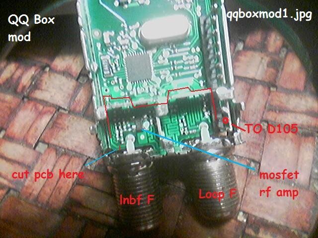
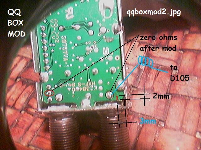
The lnbf dc voltage enters the tuner from D105 on pin 2 of the first three pin set. It travels through all three shielded compartments and has several bypass caps scattered along the way. So any hash on the line can couple to many active devices.
The first picture shows the bottom side (pcb side) of the tuner and shows the lnbf dc path. I have added detail of where to add a foil cut.
The second picture shows the top side of the tuner which is easy to access. Instructions are given to make this mod from the top side. RAVCHO's coil is shown in blue and goes to D105 lifted from the pcb as he shows or remove FB101.
Attempt this mod at your own risk of destroying the device. :rant:
Attachments
Last edited:
In your version of the mod, you do not have a decoupling capacitor, and the DC is still traveling inside the tuner. I haven't tried it yet and i don't have information whether it is good or bad. However, because of the high frequencies, generally it is not a good idea to mess with the tuner internals. Can you provide a better photo of the opened tuner? I haven't desoldered mine, and I want to see if I can figure out what is wrong with the layout.
10x in advance
10x in advance
- Status
- Please reply by conversation.
Similar threads
- Replies
- 15
- Views
- 2K
- Replies
- 12
- Views
- 2K
- Replies
- 6
- Views
- 1K
- Replies
- 5
- Views
- 1K


