Empirical Antenna Solutions

elder

SatelliteGuys Pro
Original poster
Apr 17, 2007
426
5
When my DT13 moved to VHF it was a stretch for my LaCrosse antenna. Antenna position for analog ch13 was always a multi-path battle which changed with seasons.

As I was re-pointing the LaCrosse my wife noticed that reception was better when I was touching the coax. I tried various things like grounding the shield at the feed point, but the final empirical solution was to twist a wire around the coax connector and connect the other end to a half folded dipole (J ) made of wire and inserted in the space between the planes of the LaCrosse.

Crazy, maybe but it took me from no bars to one or more on 13 and 33.
 
This homemade antenna, GrabBit Ears, is really a wonder, a gift of the LORD! It is the empirical solution to receiving ALL UHF and ALL VHF reception, and its performance is truly amazing! GrabBit Ears are a substantial improvement over current store bought designs. GrabBit Ears are the only solution that I have found to work in extreme multi-path cases. If you used to struggle with a lot of ghosting, a.k.a. muti-path interference, then GrabBit Ears will help!

If rabbit ears USED to work, then GrabBit Ears WILL work! Here's how to make them:

GrabBit Ears
 
GrabBit Ears look like my kind of antenna. I am thinking of a computer USB tuner and GrabBit Ears looks like the right antenna for that experiment.

Thanks!
 
I need to see one of these run through a proper simulation, and for that to happen, there needs to be more data. Wire gauge, for starters, feed spacing, distance from the fractals to the whiskers, etc. You can fumble into a working solution pretty easily, but whether that solution is actually better than a factory-built design is the important question.
 
I need to see one of these run through a proper simulation, and for that to happen, there needs to be more data. Wire gauge, for starters, feed spacing, distance from the fractals to the whiskers, etc. You can fumble into a working solution pretty easily, but whether that solution is actually better than a factory-built design is the important question.

Cool! I'll do what I can.

All of my research is relational to how Grabbit Ears work, versus the variety of rabbit ears and antenna that I have used in the same locations over the years.

They definitely are an improvement over the all rabbit ears I've tried including a 50 db amp RCA digital. All I know for sure is that if rabbit ears used to work, these will work. (And much easier!) They are also really good in extreme multi-path and high interference locations.

I use metal hangers. I don't know the gauge. It doesn't seem to matter which ones, or even if they're mixed types (as long as you sand the painted white ones).

I assume the feed spacing is the distance between the two halves?
1.25" +/- .25"

I haven't been real precise when I make them and they've all performed just as well in the field, and according to the converter box meter I use at home. It has a signal power reading and a signal quality reading.

The distance between the whiskers and the fractals is 3.5" +/- .25". I try to get them near 7"- fractal to fractal - after bending of the connector piece. I bend a loop at the center and each end.

I usually assemble them with small screws, washers, and nuts.

Anything else? Let me know.
Thanks!
 
I use metal hangers. I don't know the gauge. It doesn't seem to matter which ones, or even if they're mixed types (as long as you sand the painted white ones).

I assume the feed spacing is the distance between the two halves?
1.25" +/- .25"

The distance between the whiskers and the fractals is 3.5" +/- .25". I try to get them near 7"- fractal to fractal - after bending of the connector piece. I bend a loop at the center and each end.

I usually assemble them with small screws, washers, and nuts.
I just printed a b&w image from the site and assembled it myself. I used some lengths of copper wire from a left-over job installing a 120 Volt fan, 14 guage I think.

I made a loop on each end and in the middle as well, and didn't even notice at the time if you had done that on your version, so I guess great minds think alike!

Idea: I found that working with copper wire compared to a hangar was much easier to bend into the right shapes & attach with screws/washers. I guess it depends on the type of hangar. The copper was still stiff enough to hold its shape.
 
I found that working with copper wire compared to a hangar was much easier to bend into the right shapes & attach with screws/washers. I guess it depends on the type of hangar. The copper was still stiff enough to hold its shape.

Well, if you'd tried to make a 4-bay bowtie out of 14ga Romex, and made an identical unit from coat hanger wire (closer to 11ga) you'd find that there's a big difference between "works" and "works well." This perfectly illustrates the point that when you're in the UHF spectrum, EVERYTHING affects the driven elements. The downlead gauge, downlead spacing, element gauge, and element spacing are all critical, which is why I'm skeptical about this particular design.

I'm not calling ANYONE a liar, I just need to see more evidence, and I'm fully prepared to be pleasantly suprised...
What do you mean by 'works' and 'works well'? Which is which?


I get all the channels I want with the above solution - so no need to be too skeptical.

It is just as functional as the 4 bowtie version with coathangars for what I need. I don't know what's going on with channel 6 (see my tv fool posting in the other thread here).

Why don't you try making it yourself? It took me like 30-45 minutes.
 
There's a lot of stuff going on as the electrons dance along the outside of an antenna wire. The Romex version of the 4-bay does not work as well in most situations as the coathanger version, because the wires are too small, and it throws off all of the other electrical properties of the design.

To answer, "Why don't you just try it," designing and simulating it will take longer than fabricating it. The up side to doing the simulation is that once the design is done, you can adjust factors like wire gauge and element spacing in seconds, re-run the simulation, and see if one configuration really outperforms the others. So far, I've seen no simulations at all, which means that there's no empirical data to back up the anecdotal claims of this thread. If I were to just buld one and report, I'd be no different from a guy who says, "I wrapped my niece in aluminum foil, hooked her up to the TV, and she works great!"

I use 2-bay bowties in most situations, which come from a factory [in China] that makes them of heavy aluminum wire (something like 8-gauge), and are designed to be put outdoors. This $15 package also includes a reflector, mounting brackets, and a balun, which makes it pretty unbeatable when you calculate the total value of the package. A decent balun alone is $4, and it looks like there's about $4 worth of wire and fasteners in this design, not to mention the spine/backplane, which leaves about $7 worth of my time to fabricate it. This also assumes that the gain on this antenna is high enough to be useful in non-urban environments. I'm just saying...this antenna is attached to some pretty big claims.
You are making it a lot more complicated than I ever imagined for this thread. I could understand some of that for mass production and selling a product, but that's not the intent.

If you are that busy then don't do it, I was just trying to make a suggestion to help you SEE the only evidence that you can trust, it in action for yourself instead of wondering.

I gave a 'simulation' on the other thread (http://www.satelliteguys.us/digital-over-air-ota/186249-need-helping-getting-all-channels.html), did you see that one yet?

Methinks you are in a different ball-park about this - after reading your post. Since empiracal means 'relying on experience or observation alone often without due regard for system and theory', my experience and observation is that this grabit ears design works just fine, cost me no money, and made my antenna ugliness turn into an attractive hidden solution (which my wife loves).
 
I was going to say that ALL I have IS empirical data. You beat me to it bebop. What cowboy requires is STATISTICAL data. Since I haven't the equipment or knowledge, I'm hoping he will test it.

It outperforms 2-bays, but remember this is an indoor antenna. It may not perform at all out of doors. I do expect it to perform better indoors, than a 2-bay that is outdoor, though (plus you get the VHF stations).

Since I can't get any good response using my video camera and old laptop, I've instead taken some pictures of how to make the fractals. They are the most difficult bit.

I don't screw the pieces onto a board. I make two halves and then mount them on a stick or anything. I made some where I used glass patch plastic to hold them apart. Then you can stick it in the window or behind a picture, wherever works best.

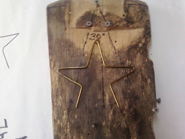
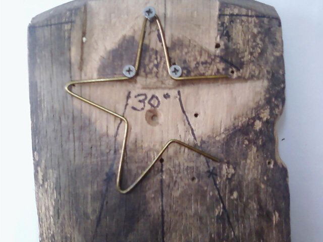
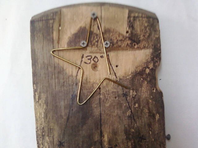
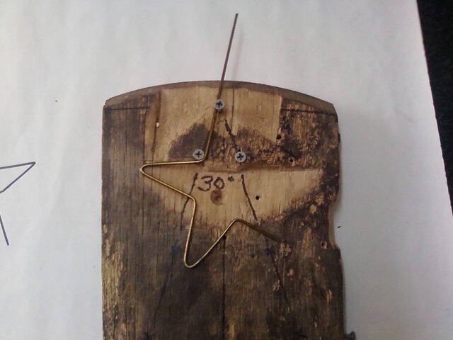
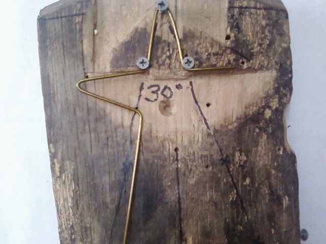
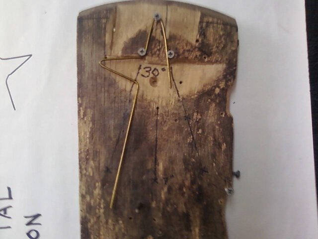
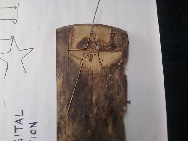
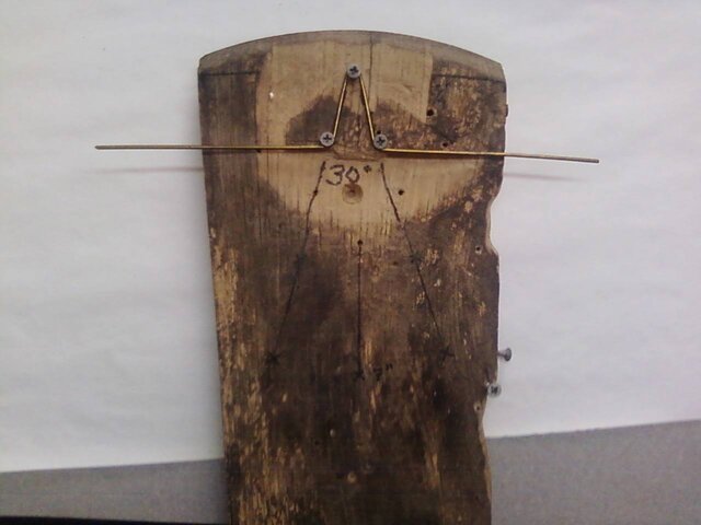
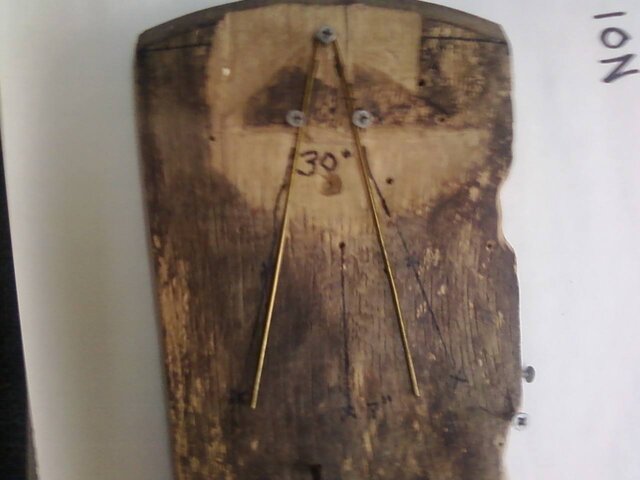
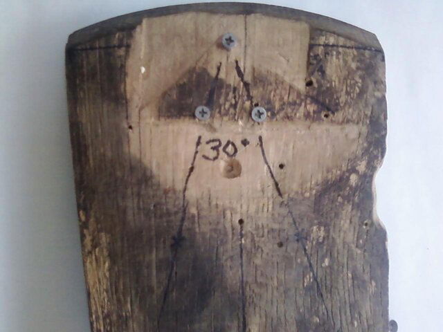
So to make the fractals I made a jig. I used three screws. Get a board and draw a 30 degree angle on it. Place one screw just inside the apex of the 30 degree angle. On both sides of the angle you drew, measure 1 and 5/8" from the apex and screw in two more screws. From there you can make easy, repeatable fractals.

I will also say that the distance between the two halves is 1 and 5/8" also. I made another one yesterday and closer than that is less effective. (Checked it just for you guys!)

Think about it though. I don't know anything except I use 14" wire to make 7" long bowties. The distance between fractal to fractal on one half is 7". The length between bends that make the fractal are 1 and 5/8". Certainly seems to me that 1 and 5/8" should be the proper distance between the halves.

1. Place your bowtie over the screw at the apex and inside the other two screws.
2. bend the remaining lengths outward back toward the apex until straight across.
3. Reposition the element.
4. Finish one side
5. Reposition the element
6. Finish the other side.
 

Attachments

  • ta da.jpg
    ta da.jpg
    67.8 KB · Views: 505
  • step8 finish bend.jpg
    step8 finish bend.jpg
    85.1 KB · Views: 450
  • step7 bend.jpg
    step7 bend.jpg
    78.5 KB · Views: 417
  • step6 reposition.jpg
    step6 reposition.jpg
    67.9 KB · Views: 460
  • step5 finish side.jpg
    step5 finish side.jpg
    113.4 KB · Views: 465
  • step 4 bend.jpg
    step 4 bend.jpg
    65.4 KB · Views: 401
  • step3 reposition.jpg
    step3 reposition.jpg
    61 KB · Views: 418
  • step2 grabbit ears.jpg
    step2 grabbit ears.jpg
    65.3 KB · Views: 577
  • step 1.jpg
    step 1.jpg
    65.3 KB · Views: 410
  • jig setup.jpg
    jig setup.jpg
    78.7 KB · Views: 457
I was going to say that ALL I have IS empirical data. You beat me to it bebop. What cowboy requires is STATISTICAL data. Since I haven't the equipment or knowledge, I'm hoping he will test it.

Wrong. What you have is ANECDOTAL data. EMPIRICAL data is backed up with research and analysis with proper metering equipment and/or lab simulation. ANECDOTAL data is the story you get from trial-and-error, which is all I've seen so far. I'm not calling you a liar, not by any stretch...I believe that you have observed good results. But you can also get good results from any number of options that aren't repeatable or even a good idea to start with (Re: Aluminum Foil Niece). Without some hard data, it's impossible to guess which situations are candidates for your antenna.

It outperforms 2-bays, but remember this is an indoor antenna. It may not perform at all out of doors. I do expect it to perform better indoors, than a 2-bay that is outdoor, though (plus you get the VHF stations).

I have to hit the BS buzzer on that one. If it works indoors, it'll work better outdoors. Adding obstructions (walls, roofing material, EMI from AC power lines) never improves reception. There are specific situations where you can introduce noise outside or introduce a phase or multipath problem that wasn't present inside the living room, but that's circumstantial.

So to make the fractals I made a jig. I used three screws. Get a board and draw a 30 degree angle on it. Place one screw just inside the apex of the 30 degree angle. On both sides of the angle you drew, measure 1 and 5/8" from the apex and screw in two more screws. From there you can make easy, repeatable fractals.

Working with a theoretical model (not actual wire) the distance between apexes should be 1-3/4", so your jig with 1-5/8" spacing sounds about right.

I will also say that the distance between the two halves is 1 and 5/8" also. I made another one yesterday and closer than that is less effective. (Checked it just for you guys!)

That's 100% inline with current practices; closer feed lines usually make things worse. But the gauge is still an unknown variable.

I've never built a simulation before, but I've bent a few antennas. I'm having a hard time with the software, but as soon as I get results, bad or good, you guys will be the first to know, and it'll be in this thread.
 
Wrong. What you have is ANECDOTAL data. EMPIRICAL data is backed up with research and analysis with proper metering equipment and/or lab simulation. ANECDOTAL data is the story you get from trial-and-error, which is all I've seen so far. I'm not calling you a liar, not by any stretch...I believe that you have observed good results. But you can also get good results from any number of options that aren't repeatable or even a good idea to start with (Re: Aluminum Foil Niece). Without some hard data, it's impossible to guess which situations are candidates for your antenna.

I'll offer this link in regards to empirical data:
define:empirical - Google Search

The application for this antenna is indoor use. It should be used to replace any situation where rabbit ears are or were used. It performs extremely well in high multi-path and high interference environments. (Which is where we are all headed anyway. I'm not guessing, I've been trying these everywhere I get a chance. They've worked when nothing else worked, or something larger had been needed. This is what I know. I've been researching low signal artifacting for three years. I've carried rabbit ears with me to help see what kind of signal a place gets to help determine what antenna might be needed.

I have to hit the BS buzzer on that one. If it works indoors, it'll work better outdoors. Adding obstructions (walls, roofing material, EMI from AC power lines) never improves reception. There are specific situations where you can introduce noise outside or introduce a phase or multipath problem that wasn't present inside the living room, but that's circumstantial.

Buzz ya back. I thought that same thing...until I took it outside. Worthless outside when I tried it. Grabbit Ears loves multi-path. (And multi-path signals are all you get inside.) It likes to be right next to a wall or a window much better than 3 or 4 or more inches from the wall or window. It lies flat very well, too.

Working with a theoretical model (not actual wire) the distance between apexes should be 1-3/4", so your jig with 1-5/8" spacing sounds about right.
That's 100% inline with current practices; closer feed lines usually make things worse. But the gauge is still an unknown variable.

I've never built a simulation before, but I've bent a few antennas. I'm having a hard time with the software, but as soon as I get results, bad or good, you guys will be the first to know, and it'll be in this thread.

I didn't realize you were working on simulation data. I thought you could build one and test it. Test data is the information I'm most interested in.
 
Touché. I've been running with engineers for so long, and their definition implies proof of theory, beyond just tinkering blindly. I stand corrected.

I will continue working on simulations, though, and keep you posted as progress is made. Who knows, maybe you have stumbled upon the better mouse trap. It's just that I have a real problem with stumbling in the dark when there's a perfectly good lantern available. :)
 
Last edited:
I was going to say that ALL I have IS empirical data. You beat me to it bebop. What cowboy requires is STATISTICAL data. Since I haven't the equipment or knowledge, I'm hoping he will test it.

It outperforms 2-bays, but remember this is an indoor antenna. It may not perform at all out of doors. I do expect it to perform better indoors, than a 2-bay that is outdoor, though (plus you get the VHF stations).

Since I can't get any good response using my video camera and old laptop, I've instead taken some pictures of how to make the fractals. They are the most difficult bit.

I don't screw the pieces onto a board. I make two halves and then mount them on a stick or anything. I made some where I used glass patch plastic to hold them apart. Then you can stick it in the window or behind a picture, wherever works best.

So to make the fractals I made a jig. I used three screws. Get a board and draw a 30 degree angle on it. Place one screw just inside the apex of the 30 degree angle. On both sides of the angle you drew, measure 1 and 5/8" from the apex and screw in two more screws. From there you can make easy, repeatable fractals.

I will also say that the distance between the two halves is 1 and 5/8" also. I made another one yesterday and closer than that is less effective. (Checked it just for you guys!)

Think about it though. I don't know anything except I use 14" wire to make 7" long bowties. The distance between fractal to fractal on one half is 7". The length between bends that make the fractal are 1 and 5/8". Certainly seems to me that 1 and 5/8" should be the proper distance between the halves.

1. Place your bowtie over the screw at the apex and inside the other two screws.
2. bend the remaining lengths outward back toward the apex until straight across.
3. Reposition the element.
4. Finish one side
5. Reposition the element
6. Finish the other side.
Great idea. Thanks for the follow-up instruction. I just free handed the fractals for my first attempt. I'm sure I'd get better results if I made them uniform and proper spacing. If I ever get some time I might try it this way. I'm big on pictures, so those help the most.


Forgive me if I missed it, but what is the distance between the two ends of one fractal after it is all bent into shape?
 
I have to hit the BS buzzer on that one. If it works indoors, it'll work better outdoors.

You're right CowboyDren! I was way wrong on this one!

Grabbit Ears DO work much better outside. My problem was I was trying to use them "vertically" the way they hang inside. Using them this way is only a little better and they are somewhat directional.

Then it hit me to try them flat. WOW! Omnidirectional too.

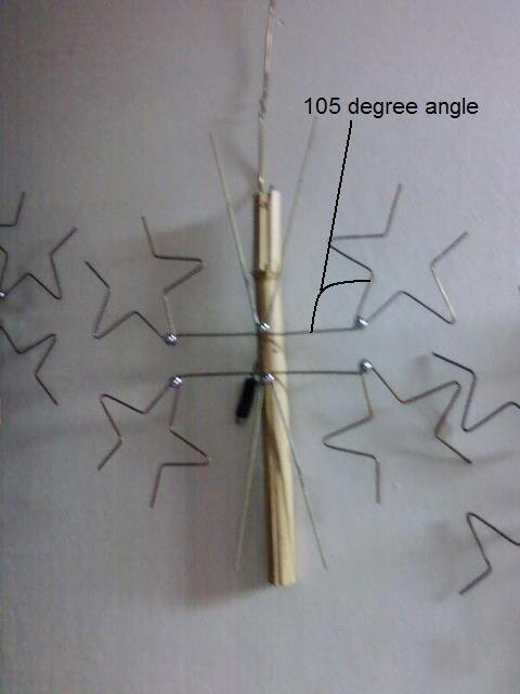
And from the last "batch" I made, I think I've discovered a detail that I missed. The fractals are not "perpendicular to the feed lines. They are angled out from the center at about 105 degrees. Picture added.
 

Attachments

  • Grabbit Ears angle.JPG
    Grabbit Ears angle.JPG
    22 KB · Views: 676

Users Who Are Viewing This Thread (Total: 0, Members: 0, Guests: 0)

Who Read This Thread (Total Members: 1)

Top