Design & Construction of Offset Dish

Status
Please reply by conversation.
I would think flat white would be ideal. It shouldn't be reflective enough to cause a lot of heat on the feed.
As long as it's not shiny!

I used to have a spun-aluminum c-band dish back in the day. Paint it a flat CREAM color, (mine was) and it will stay cool, and won't look bad. White and silver will generate a lot of heat at the lnb, depending on where it's pointing, time of year, and where the sun is at. Cream doesn't seem to have that issue. Don't leave it silver! Unless you want a solar cooker.
 
The aluminum lamina finally arrives and work intensifies.

Dreams now involve night sweats and visions of that old movie " Flight of the Phoenix".

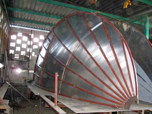
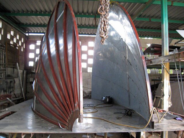
Thumbnails are of beginning alignment of the assembled parabolic halfs, checking the lamina fit in the upper areas of the antenna by using the master rib form and a sheet of thin formica, and the two plane pivot point assembly. Things are looking good. Now work will begin using the actual aluminum lamina along with reinforcement as needed.

From the thumbnail on the right, it looks like the pivot point is on the edge of the dish, not in the center. Is this correct?

How will the aiming and adjustment be done?
 
From the thumbnail on the right, it looks like the pivot point is on the edge of the dish, not in the center. Is this correct?

How will the aiming and adjustment be done?

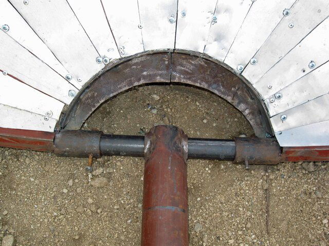
The pivot is at the vertex ( toe). It will pivot in two planes at that location. Rotation, and elevation mechanism support will be at the rear. Rotation support will be on a wheeled system that will track on a flat surface. Elevation adjustment will be a convention screw adjustable support system attached to the wheeled support system. Since it rests on it's toe, the rear support system will not need to be massive.

This design eliminates the need for heavy structural reinforcing in the center area of the antenna. And, the lnb will be closer to the ground level.
 
Separation

The lamina is on and the two parabolic halfs have had their temporary welded construction connections removed. Current work involves fine adjustments of the lamina, removing minor dings, and alignment checks. Next step is adding the removable attaching mounts which connect the two sections, doing a test assembly and another alignment check.
 

Attachments

  • Half Rear View Lamina Installation.jpg
    Half Rear View Lamina Installation.jpg
    358.7 KB · Views: 360
  • Two Halfs Lamina Installation.jpg
    Two Halfs Lamina Installation.jpg
    329.9 KB · Views: 346
The pivot is at the vertex ( toe). It will pivot in two planes at that location. Rotation, and elevation mechanism support will be at the rear. Rotation support will be on a wheeled system that will track on a flat surface. Elevation adjustment will be a convention screw adjustable support system attached to the wheeled support system. Since it rests on it's toe, the rear support system will not need to be massive.

This design eliminates the need for heavy structural reinforcing in the center area of the antenna. And, the lnb will be closer to the ground level.

All of the radials meet at the toe, so that makes sense.

After reading about the wheeled support system, I wonder how the structure will attach to the ground besides at the toe...?

Also, where or at how many points will the elevation support connect to the dish?

How about posting a sketch?
 
Nelson;

Very, Very impressive.

Gearing or rubber tires for going around the track? I'm imagining a central pivot point like a trailer axle.

Still working on those details but it will probably be hard rubber or steel tires. Probably will have some sort of inching screws on tiedowns for final adjustment. Elevation will be similar, probably with two slotted sliding side supports that will be left loose until elevation is fixed and a central adjusting screw for alignment. Needs the two side supports for stabilizing in wind but can not use them for alignment since uneven racking would warp the antenna. Will have it all figured out and in the fab shop in the next week or so.
 
In Cyprus my 3m spun aluminum dish on Astra 28east actually points around 190 degrees, unfortunately with its elevation there is a couple of weeks a year where the sun, satellite and lnb all line up for about 3 minutes and signal blacks out completely.
Bearing in mind the ambient temperature at that time is around 38-45C a probe on the LNB horn gave a maximum temperature of 73C when the dish was military grey as opposed to 64C when cream. The LNB is an invacom QTF031with a ADF120 horn.

That answers my question. Looks like cream is the color. Have you looked at Klaus Schumaker's parabolic antenna re: your 3M problem?. One of the suggestions there was to strap a a thermoelectric cooler on the lnb. Cheap fix if it works. I was able to replicate their refrigeration test. I've got the parts on order and am going to give it a try. I also put alumininum reflective facing on my lnbs to knock down the heat load.
 
One of the suggestions there was to strap a a thermoelectric cooler on the lnb. Cheap fix if it works. I was able to replicate their refrigeration test. I've got the parts on order and am going to give it a try. I also put alumininum reflective facing on my lnbs to knock down the heat load.

I'd be interested to hear how you get on with that - my cooling method was far more primative I am ashamed to say. Because there was the World cup soccer series during the outages I used a feed from our small bore watering irrigation system over the aluminium feed horn and mount.
 
First Assembly

A new year and back to work.

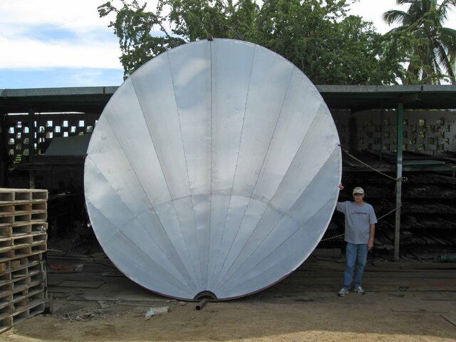
Thumbnails of the first assembly and the pivot base point.

Down to the paint shop for eight liters of anticorrosive paint

The aluminum sheeting comes with a protective film on the polished side. When it is removed and before painting, imperfections and misalignments are easy to see with a flashlight shining across the antenna or in bright light. Just like the carnival mirrors, everthing is magnified.
 

Attachments

  • First Assembly.jpg
    First Assembly.jpg
    335 KB · Views: 376
  • Piviot Base.jpg
    Piviot Base.jpg
    518.5 KB · Views: 329
Wow, for some reason, I thought you were making a 6' dish. If so, you're not very tall, are you? Bottom line, I'm jealous! Looking very good nelson.
 
Man, it's huge and heavy to move it around ... What weight it has now?

Coming from polishing glass lenses experience, how you will hone each sheet to bring total curve to parabolic shape ?
It should be done before painting.
 
nelson, that's an awesome looking dish...

Coming from polishing glass lenses experience, how you will hone each sheet to bring total curve to parabolic shape ?

Maybe installation of some constant radius hoops around the toe might mitigate potential for flat spots between the parabolic radials... Kind of like how Paraclypses handle this...
 
quote=Smith, P.;1653579]Man, it's huge and heavy to move it around ... What weight it has now?

Coming from polishing glass lenses experience, how you will hone each sheet to bring total curve to parabolic shape ?
It should be done before painting.[/quote]

I'm going to weigh it before putting it up but I'm guessing not much maybe something like 200-300 lbs. The cold formed steel tubing keeps the weight down.

The parabola was set by the ribs. Within the 10 degree rib spacing, the aluminum sheeting flexes to fit the curve. I used relatively thick sheeting to keep the surface from warbling. I return frequenctly to check the surface with the master rib pattern. And you are correct. Once the paint is on, it will be very difficult to detect where the problems are. I'm really nervous about that.


4.5 meters = 14.8 feet

Hope it doesn't get windy!

It's an offset so the 14.8 is diameter. Just shy of 16 feet tall.

Wind definitely is a concern. I've seen 1.8 M Channel Masters that are built like a tank ripped off their mounts and blown away.

Going to nestle it up next to a wall and close to some other structures to minimize wind effect. And, with the pivot point on the toe, I will be able to flip it over and tie it down for the really big winds. A total of 6 or 8 bolts hold it all together. Everthing else is welded.
 
Brilliant Nelson. Just a thought , I am sure you have calculated the focal point but you can check this relatively easy for real on a full moon (or near) night before the surface is painted and adjust the surface for scatter. You just need moon elevation from your QTH the LNB arm a cardboard disc and a small hole in dish to line up.
 
WOW that is awesome. I absolutally love it! I just have one question will a hh 90 move it lol!!! Just kidding good luck with your testing.
 
Status
Please reply by conversation.

Installer resource

where can i get a new diseqc motor

Users Who Are Viewing This Thread (Total: 0, Members: 0, Guests: 0)

Who Read This Thread (Total Members: 1)

Latest posts