Design & Construction of Offset Dish

Status
Please reply by conversation.
The thought of building a dish came up in a recent thread and someone suggested a type of 'fence' being built (stationary) with a moveable feed assembly.
That thought has never left my mind, but, I had an additional thought... instead of a moveable feed, why not multiple feeds?
Assuming a 'fence' of this type was built, just how much of the arc could be received before one end of the fence interferes with the other? I would assume this would be the same regardless of size... however, I guess, it would vary depending on your latitude...


14karat:

We could start another thread on this subject. What you described is the Swan Spherical Antenna. Like the first homebrew satellite hobbists built. They were oriented along an East/West line. Were typically eight feet high and twelve to sixteen feet wide. The focal point for the due south satellite was usually twelve feet or so in front of the center of the "dish". The top of the "dish" was tilted so as to put the focal point at a comfortable height, usually eye level. Closer to the equator the "dish" tilted away from the focal point, further from the equator the "dish" tilted towards the focal point. During the construction a string or a wire was stretched from the focal point to the surface of the "dish" which was made adjustable by allthread rods. The surface of the "dish" was made from 1/2" thick X 1 1/2" wide redwood strips attached to the end of the allthread rods which were attached to a rigid frame on the other end made of 2"X4" or angle iron. After the spherical surface was adjusted to the string, it was covered with aluminum window screen. See the attachment for a picture of one that was constructed in Alaska back in the 1980's.
 

Attachments

  • Spherical.doc
    159.5 KB · Views: 449
That's a pretty cool dish, even though it's huge it seems very functional.
And the fact that it's 18' to work in Alaska, considering the low power of satellites in the 80's, would indicate that a similar design would not need to be so big in the lower 48 (and the more populated regions of Canada). That's something that if built properly could work well as a one dish C-band solution with no need for moving parts! Instant channel changes for FTA and 4DTV, sweet!

NOTE TO ADMINS: Is it possible to combine these posts on Spherical Antennas into another thread so that we don't hijack this thread?

The spherical can be made more rectangular with a much more lower profile and disguised as a rose or bean trellis for HOA compliance. Using window screen, it would work for Ku. Back in the 70's and 80's when C band was the only consideration, 1/4" hardware cloth was often used as the reflective surface. Another point is that these things have to be much larger that first realized because the spherical surface is only about 20% efficient as compared to a parabolic. The technical term for the lower efficiency is spherical aberration (Google that one), which relates to some of the electromagnetic waves (microwave signals) arriving at the focal point out of phase.

Harold
 
Might be hard to hide the feedhorns which would seem arbitrarily placed about the lawn and yard but I like the idea a lot.
Add that to the list of "things I'd like to do when I have some spare time" hah!
Another project which would help me construct one of these is a CNC router. Again a backburner project. Life/work keeps getting in the way of these cool projects.
 
Fabrication

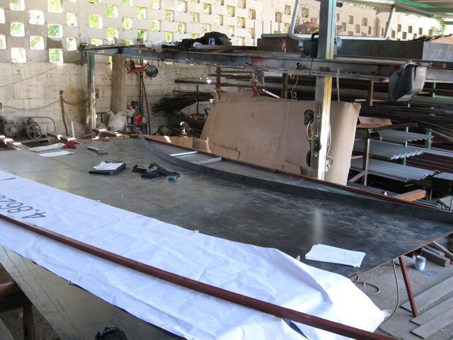
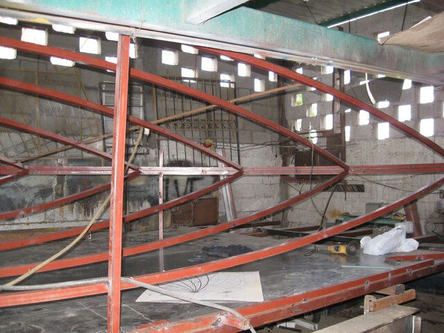
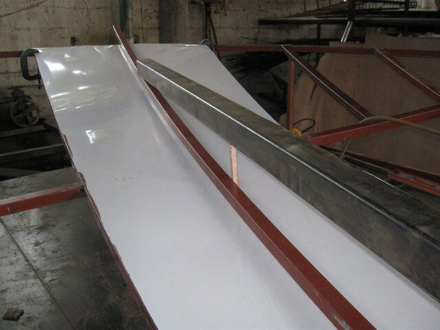
So now I am in the fabrication process. My trusty right hand man promptly informed me that we had to build a 6 by 3 meter, steel bed, work surface (flat- flat- flat) to obtain the precise measurements and alignment required. Then down to the local print shop where they plotted out the exact, full scale pattern parabolic curve on a 6 meter by 1 meter drawing along with the full scale petal pattern cutout diagram.

The master rib was then cold formed to exactly match the pattern.

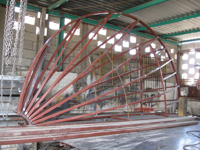
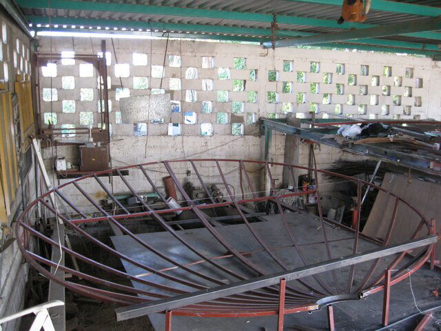
Three thumbnails show the bed and start of the initial rib, the two mirror halfs of the antenna assembled in a clam shell horizontal and the third showing the two mirror halfs in a clam shell vertical.

Current work involves deciding where to reinforce the structure with cross struts, work on the support and adjusting structure, and the arrival of the aluminum surface plating.
 

Attachments

  • IMG_0012.jpg
    IMG_0012.jpg
    921.7 KB · Views: 345
  • IMG_0040.jpg
    IMG_0040.jpg
    1.1 MB · Views: 323
  • IMG_0042.jpg
    IMG_0042.jpg
    1.1 MB · Views: 602
Sorry Caddata, my point wasn't to hijak...
In post #16 Nelson was discussing how big and heavy the dish design would be and what measures to take to make it moveable... I was just pointing out a massive collector could be had with no movement at all... just need the real estate.
Inno, my thought for the feedhorns... lawn lighting!
(I am, however, seriously considering this as a future project...)

I liked the spherical antenna info. It makes one think of alternatives. The best ideas I run into seem to come from work people did decades ago - we all work to reinvent the wheel.
 
Progress Report

The aluminum lamina finally arrives and work intensifies.

Dreams now involve night sweats and visions of that old movie " Flight of the Phoenix".

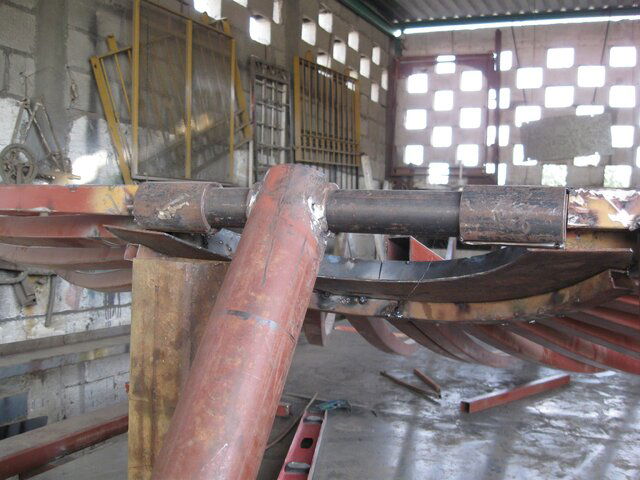
Thumbnails are of beginning alignment of the assembled parabolic halfs, checking the lamina fit in the upper areas of the antenna by using the master rib form and a sheet of thin formica, and the two plane pivot point assembly. Things are looking good. Now work will begin using the actual aluminum lamina along with reinforcement as needed.
 

Attachments

  • IMG_0054.jpg
    IMG_0054.jpg
    1.1 MB · Views: 306
  • IMG_0056.jpg
    IMG_0056.jpg
    705.7 KB · Views: 271
  • IMG_0058.jpg
    IMG_0058.jpg
    918 KB · Views: 260
Wouldn't be get more _efficient_ antenna by using parabolic surface, rather then spheric one ? ;)

I'm a week or so late getting into reading this interesting thread, but just thought I'd add something. It's been a couple years since I struggled through this thought process, but actually, I think that the surface of a TVRO dish should be an ellipse, not a parabola. Astronomical telescopes use parabolic mirrors since they're looking at something essentially infinitely far away, but satellites are not at infinite distances, and really the surface that would result in a perfect focus would be better described as an ellipse. However it would be an EXTREME ellipse, which is essentially the same as a parabola.
Doesn't have any affect on this discussion, but it's something interesting to think about.
 
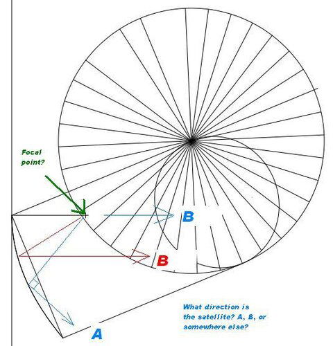
If you look at the PDF in this post, the offset dish appears to be a projection of part of a prime focus dish. That makes sense, I suppose.

From the attached image of the PDF, there appears to be a focal point defined. If this is the proper place for the focal point, I have a question:

What direction is the satellite in relation to the focal point?

Otherwise, how does the geometry work? (aiming of the dish with respect to the focus)
 

Attachments

  • offset.jpg
    offset.jpg
    42 KB · Views: 276
If you look at the PDF in this post, the offset dish appears to be a projection of part of a prime focus dish. That makes sense, I suppose.

From the attached image of the PDF, there appears to be a focal point defined. If this is the proper place for the focal point, I have a question:

What direction is the satellite in relation to the focal point?

Otherwise, how does the geometry work? (aiming of the dish with respect to the focus)

Draw the rest of the prime focus dish in sideview. The focal point for the offset dish is at the same location as the prime focus dish it's cut from. Look at the diagram in reply #9 of this thread.

Harold
 
Draw the rest of the prime focus dish in sideview. The focal point for the offset dish is at the same location as the prime focus dish it's cut from. Look at the diagram in reply #9 of this thread.

Harold

Thanks for explaining. Apologies for the redundant post. I disregarded the Word .doc file in post #9. My Office application is ancient and unpatched. To open Word files is like playing Russian Roulette.

PS. Yeah, I know about Open Office and standalone Word viewers.
 
Cutting and Installation of Lamina

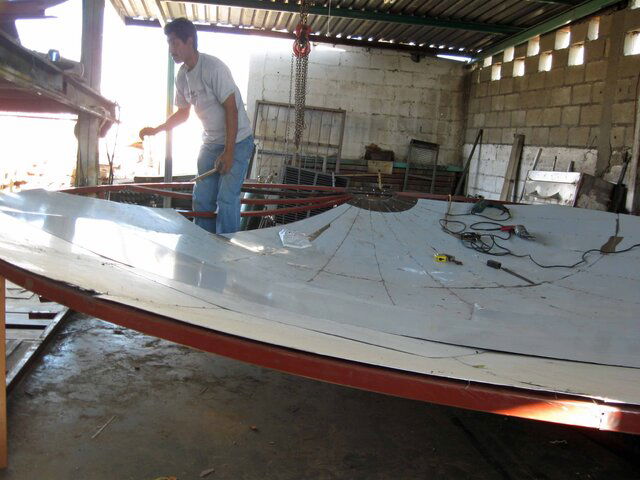
Spent the last couple of weeks on the cutting and installation of the surface (lamina). Aluminum sheeting - 16 gauge. Could have gone much thinner but had concerns with dimpling or random damage in the future with thinner surface. Next, a return to the master rib and rechecking and adding fasteners to bring the surface into final alignment, fabricating fasteners to attaching the two parabolic halfs together, fabricating the remainder of the support system, fabricating lnb arm, and paint.

Color: This thing can be downright dangerous with the heat load it can generate. I've been assuming that the flat gray on most antennas was chosen because it has the lowest heat reflection to the lnb while not creating a heat sink on the antenna surface. Any ideas on paint would be appreciated. I'd paint it pink if it would perform better
 

Attachments

  • Lamina.jpg
    Lamina.jpg
    312.8 KB · Views: 292
Status
Please reply by conversation.

Installer resource

where can i get a new diseqc motor

Users Who Are Viewing This Thread (Total: 0, Members: 0, Guests: 0)

Who Read This Thread (Total Members: 1)