Thought I might share some work in progress on the design and construction of an offset dish (a little bigger than most would use).
As most obsessions, this one started out as a minor irritant ( I lost reception on some transponders due to low signal levels).
That led to the world of satelliteguys.us and the associated technology discussed in the forums. Stuff like line losses, dBm, receiver thresholds and noise levels (noise is really important with low signal levels).
That led to the need to know the radiation levels in my receiving area. Onward from there to learning about the FCC data bases, finding the digital data for EIRP's and converting it into Google Earth format ( this is really neat since you can overlay satellites and transponder EIRP's for any geographic point in the FCC data base on the google earth model and rotate and zoom to your hearts content).
All that "stuff" convinced me that I needed a "BIGGER DISH". AHH, the dream of every addict.
On again to more searches on the principles of offset antennas and the associated formulas. And, a side trip to learn how to use AutoCad . This mother has to have tolerances that could be used on the Hubble (I wish).
Now for some modeling to aid in construction design.
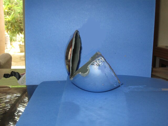
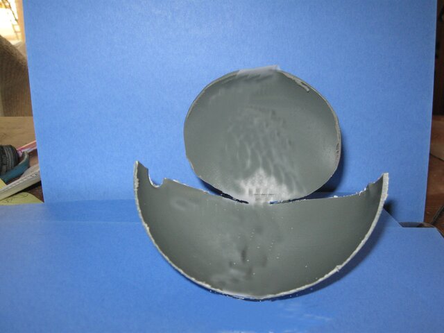
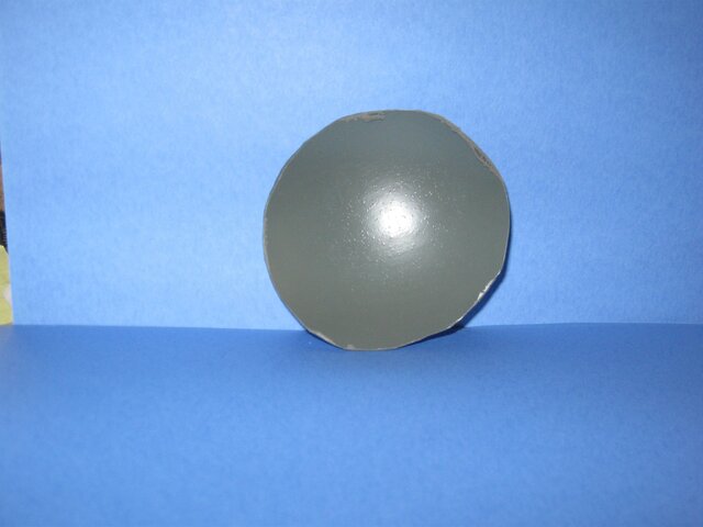
I needed to visualize what I needed to do and started out with half of a 5 inch model ball which simulated a prime focus antenna. Then I cut it up to illustrate the part that would be used for the offset antenna.
The math all works out that (more or less) when you cut an offset out of a 0.3 F/D prime focus you end up with a offset antenna with an F/D of 0.6.
Model pictures attached .
Next, I'll get into design layout and construction (in progress).


