10' CM Perf on AJAK H180

Status
Please reply by conversation.
The wiper arm fits over the shaft onto the cone shaped area and a nut secures it down. If the blade is frozen to the glass that fitting will break loose rather then bend up a wiper arm.

I meant a 24V "motor" should be OK ;)

The load on the motor varies with cold temps and snow and what position the dish is in. But for the most part stays very close to 2 revs per second
 
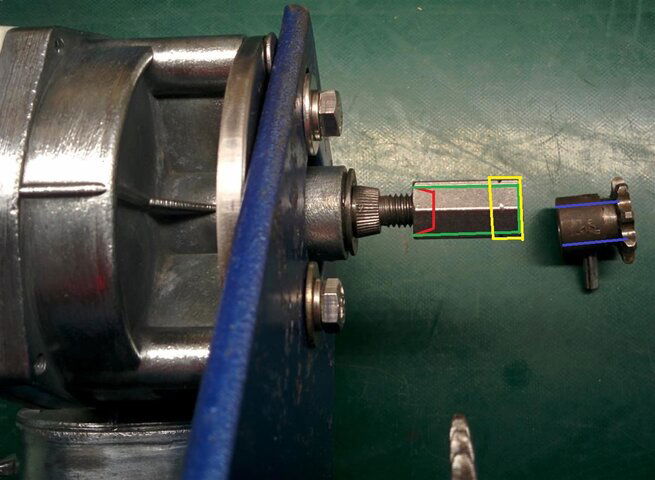
I think I will use long nut. Will make it conical from inside (red lines) to maximally fit shaft cone. Then will make long nut cylindrical (green lines), leaving only yellow part to be able to tighten the nut on the shaft. If necessary, will make hole little bit bigger (blue lines) to perfectly fit cylindrical part of the long nut. When everything is tightened, will drill the hole for the pin or screw.
IMG_20160515_004114 (Custom).jpg
 
I've been so far unable to find that post again that talked about the Ajak motor. I still have hopes I'll find it, if it's still on the web. It might have been on Rick's site, and mentioned as part of an entire thread. Not sure, but I do know I did see and read it at one time for sure.
 
I think I will use long nut. Will make it conical from inside (red lines) to maximally fit shaft cone. Then will make long nut cylindrical (green lines), leaving only yellow part to be able to tighten the nut on the shaft. If necessary, will make hole little bit bigger (blue lines) to perfectly fit cylindrical part of the long nut. When everything is tightened, will drill the hole for the pin or screw.
View attachment 116678
I am curious what you have figured out for the sensor? Where and how to mount it?
 
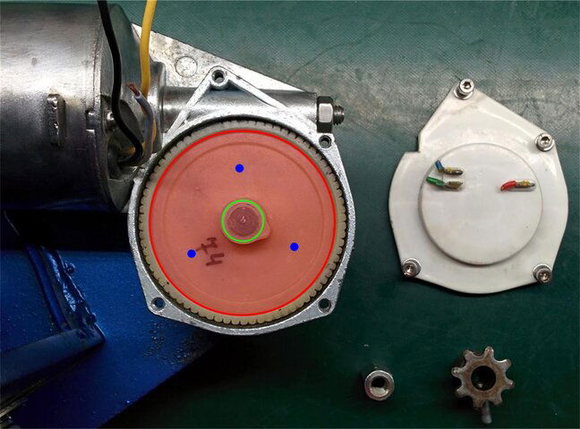
I do not see any issues here. There is enough place to insert any wheel with magnets or slots for optical sensor. Red circle represents possible wheel to be inserted. It can be attached to main shaft along the green circle or even by several screws (blue) to the main wheel. But this I will do after chain cog-wheel is attached.
MagnetWheel.jpg
 
  • Like
Reactions: Magic Static
I found a link years ago that explained where the motors came from. Let me try to find it again. If I remember right, they were a motor used in a particular truck. Maybe for windshield wipers? I can't remember for sure.

By looking at previous pictures, it sure does look like a wiper motor. They are available in 24VDC for sure.
There are also 24VDC Marine grade wiper motors available too, but they are way more expensive than the truck models. 24VDC wiper motors seem popular these days for making DIY electric bicycles too.

Anyone have any manufacturer markings or numbers on the motor body to share?
 
By looking at previous pictures, it sure does look like a wiper motor.
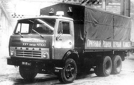
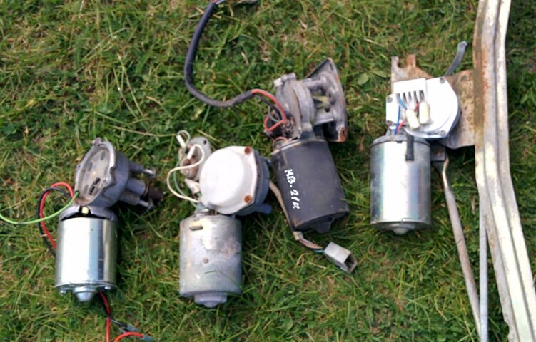
Indeed, the motor I am trying to adopt to Ajak came from KAMAZ truck, something like this kamaz-5320-01.jpg I was actually took lessons and got my driver's license on this car, but that was many many moons ago :angel. Last Friday, when I went to scrap-yard, there where many of wiper's motors. There are left and right versions available. I took 3 of them just to examine and test which is better IMG_20160513_132125.jpg . One of them perfectly fitted to Ajak, but that was 12V. So, at the end I chose 24V version but needed some adjustments to install it. .
 
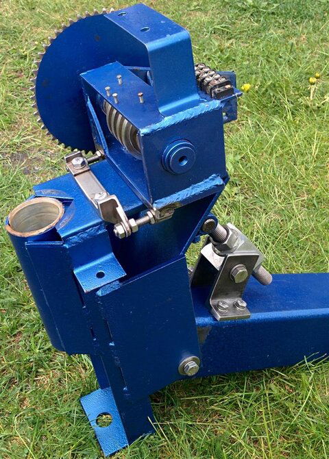
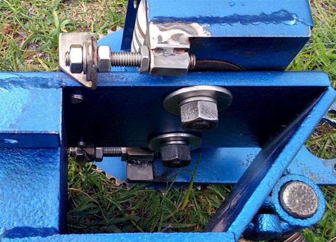
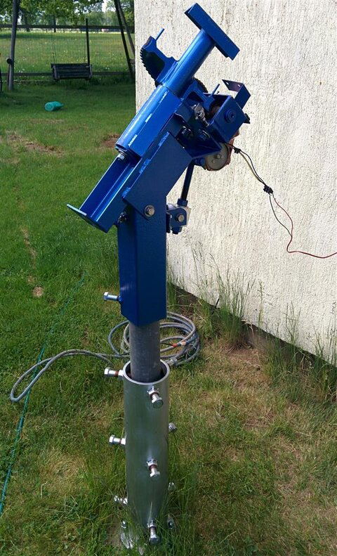
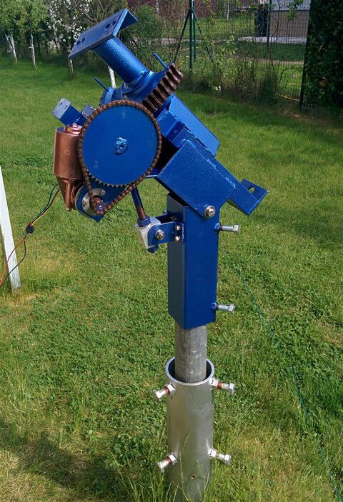
Have made mod for fine adjustment of the worm-gear, will see how it works when electrical motor up & running. Of course, after all these "manipulations" will need to repaint everything (anyway, I have some blue paint left). IMG_20160516_112125 (Custom).jpg IMG_20160516_112202 (Custom).jpg
 
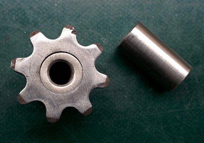
Have attached cog-wheel to the shaft. Did the following:
- drilled 12mm hole in the cog-wheel (there was 11mm hole originally);
- took INOX long-nut with 8mm thread inside and made it 12mm round;
- inserted long-nut inside the cog-wheel and welded them together;
- drilled 5mm hole through this "sandwich" and made 6mm thread in it;
- angle-grinded cog-wheel body from 2 sides to be able to tighten it with 17mm wrench.
So, new motor is working fine, and, as I have said before, it has 2 speeds. Should think now how to wire everything to use 2-speed possibility :what
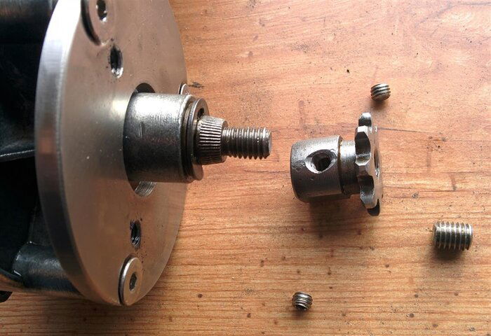
After cog-wheel is tightened to the shaft, it is fixed by 2 small 6mm screws (gently, to not damage shaft thread) and 8mm screw, which is screwed inside the cog-wheel.
And, also made INOX horse-shoe washer for motor tightening to the mount.
IMG_20160516_211738 (Custom).jpg IMG_20160517_074818 (Custom).jpg IMG_20160517_075331 (Custom).jpg
 
Impressive work RimaNTSS! :yessign

I've been keeping an eye out for an H2H motor while cruising for a larger dish.After seeing all the work you are putting in to revive one,I'm not so sure I want to find one now.lol.
 
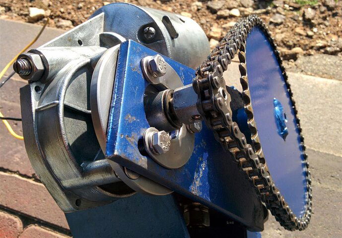
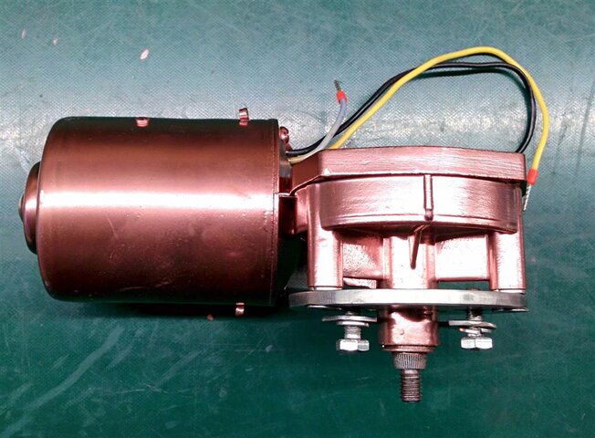
As promised, painted new electrical motor in copper, looks strange, but at least something different from navy-blue :) . IMG_20160517_213615 (Large).jpg
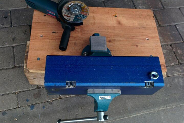
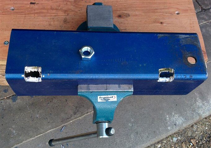
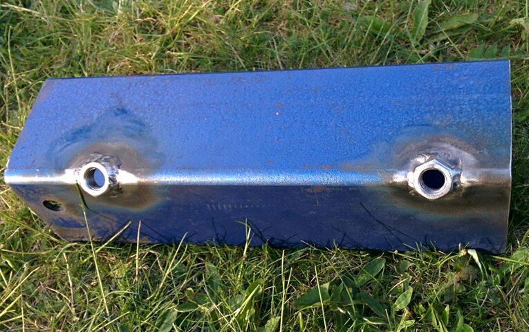
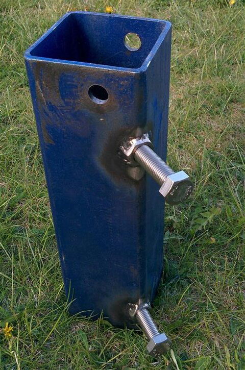
Welded 2 nuts to the vertical square pipe. IMG_20160517_173756 (Large).jpgIMG_20160517_175419 (Large).jpg IMG_20160517_191229 (Large).jpg IMG_20160517_192158 (Large).jpg
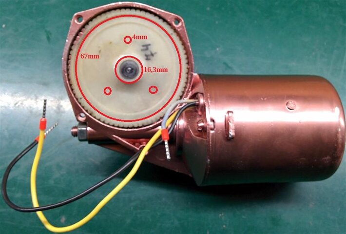
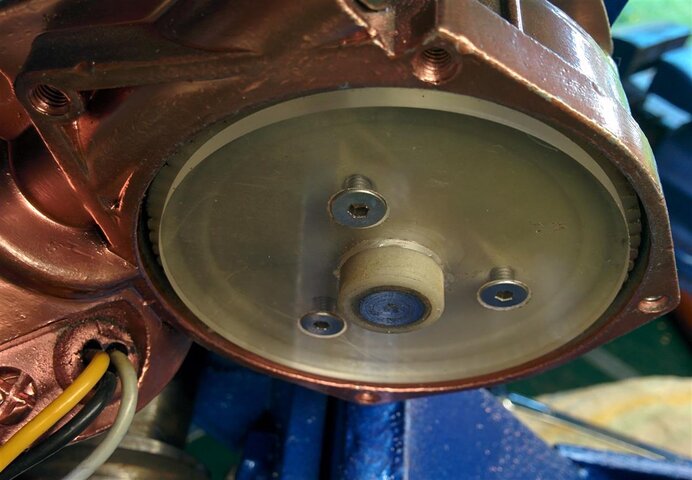
Magnet-wheels I will be making 67mm in diameter with central hole 16,3mm. Was trying to drill the hole in the main shaft, but it tempered, so, no way. Magnet-wheels will be attached to the worm-gear by 3 x 4mm screws. IMG_20160517_213708 (Large).jpg

P.S. @aremadillo_115 In reality, majority what I am doing is just for fun, and it might be not necessary if you get HH motor in working condition.
 
  • Like
Reactions: Jason S and KE4EST
So what are your thoughts on the declination adjustment on this AJAK, 5 fixed positions 4°~8°. You were going to use this for an offset dish right?
 
Thinking about the 24V motor and the three wires. One wire is Ground and the other two are Power. Connect one and you get slow speed, connect the second and a faster speed. If you connect all three do you get a third speed?
 
If you connect all three do you get a third speed?
Nope, any other combination of wires gives almost shortage. But slow speed is not a problem, I can try to increase voltage or make little bit bigger cog-wheel. Now Ajak goes from H to H in approximately 4 minutes. Yes, brought the motor to the fresh air :)
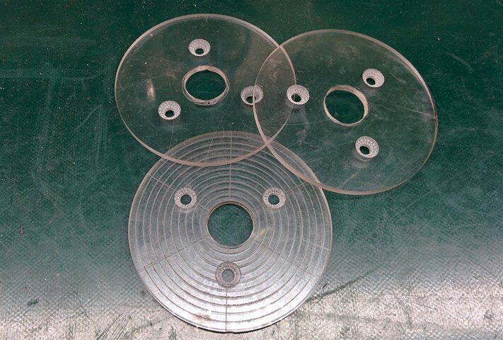
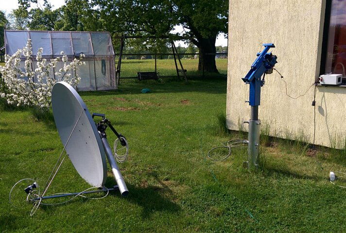
Made several 72mm magnet-plates, just in case I wish to experiment with different magnets and reed-switches. There is short video of the working beast.
Did not think a lot about declination adjustment, will do that when time comes.
 

Attachments

  • IMG_20160518_145946 (Custom).jpg
    IMG_20160518_145946 (Custom).jpg
    111.9 KB · Views: 151
  • IMG_20160518_150214 (Custom).jpg
    IMG_20160518_150214 (Custom).jpg
    174.6 KB · Views: 149
  • IMG_20160518_153947 (Custom).jpg
    IMG_20160518_153947 (Custom).jpg
    162 KB · Views: 146
  • IMG_20160518_154037 (Custom).jpg
    IMG_20160518_154037 (Custom).jpg
    188.5 KB · Views: 175
  • IMG_20160518_155356 (Custom).jpg
    IMG_20160518_155356 (Custom).jpg
    241.9 KB · Views: 164
What I am thinking now is same issue: How to adjust the worm-gear?! Mechanism, I've made for this purpose, is working fine, but only problem is- I can not feel where is proper position of the worm. Perhaps I should measure amperage, for sure amperes are different on the different positions of the gear. By adjusting the gear I should make amperes stable during all travel from H to H. That is the theory.
 
What I am thinking now is same issue: How to adjust the worm-gear?! Mechanism, I've made for this purpose, is working fine, but only problem is- I can not feel where is proper position of the worm. Perhaps I should measure amperage, for sure amperes are different on the different positions of the gear. By adjusting the gear I should make amperes stable during all travel from H to H. That is the theory.
You could use a compound that mechanics use for setting up differentials showing the contact pattern between the gears.
Been so long I thought about that I forgot what the stuff was called but it comes to me now. "Prussian Blue" Permatex makes it. You might be able to use a substitute maybe?
 
Last edited:
Status
Please reply by conversation.

Users Who Are Viewing This Thread (Total: 0, Members: 0, Guests: 0)

Who Read This Thread (Total Members: 8)

Top