WSI Vbox X Relay Stuck??

Status
Please reply by conversation.
Those rectangular thingies are your 12v and 5v regulators.
Next questions yes and yes High probability that will be the case

The VBox X doesn't have those transistors that KE4EST was thinking of.
 
Has to have a transistor array chip then. :)

The one I have is EXACTLY like the picture that Magic posted on the other page. He had mentioned that he took the guts out of that plastic housing and mounted it in a metal one to aid in heat dissipation I think?

The Vbox 7 has a different board but most of the components look to be the same, just in different places.

EDIT, looks like he posted it again while I was composing this post.
 
I thought I had something there but was I on the wrong track. I wish I had the schematic for the VBox X.
 
Hey Magic, they only got 6 of them listed and all with different values? So which one do I need? And can it be found on fleabay instead?

Swapping that West relay didn't fix that one as it still runs West as soon as it's plugged up? :(

Vbox 7 doesn't have a transistor array chip, but, that Moteck Vbox II DOES. :rollingeyes Which makes it a Vbox X CLONE IMHO! :facepalm All the same parts and firmware, just in different locations on the board. And the transformer in the Moteck Vbox II is exactly like the one in the Vbox 7. The old Vbox X ones look completely different.

Thanks

EDIT: Dang, looks like he posted before me yet again? Huh!
 
Well looking at the ICs on that board, you got a 16 pin above the display and that should be the display control, The 28 pin main controller, The 8 pin to the right of that which is EEPROM probably for user stored info. and that leaves the 14 pin above those. Not sure what it's doing but not thinking it's a transistor array either. So the main control can power the relays without transistors?? I don't see any other components that are unknown as to their function.
 
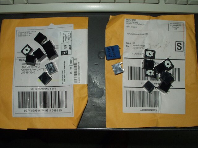
Well, I finally got those relays today and guess what? The old redneck saying "Hey Ya'll, watch this" probably applies here as the dumba$$es sent the WRONG relays yet again, only this time they sent 10 instead of 8?? So now I got 18 relays that won't fit anything I have?? You just couldn't make this sh*t up??

http://www.ebay.com/itm/221879686239?_trksid=p2060353.m2749.l2649&ssPageName=STRK:MEBIDX:IT

wrong_relays_again.jpg
 
Well, I finally got those relays today and guess what? The old redneck saying "Hey Ya'll, watch this" probably applies here as the dumba$$es sent the WRONG relays yet again, only this time they sent 10 instead of 8?? So now I got 18 relays that won't fit anything I have?? You just couldn't make this sh*t up??

http://www.ebay.com/itm/221879686239?_trksid=p2060353.m2749.l2649&ssPageName=STRK:MEBIDX:IT

View attachment 119830
Interestingly enough you now own more relays than you will ever need that fit the Titanium ASC1 They are smaller in size than what you have but that is indicated in their ad with a metric ruler.

relays.jpg
 
Last edited:
Part of the DiSEqC decoding circuit. I'll bet money it is a LM339.

Yup, that's the P/N on it all right, and, all three of these Vboxs have that same one in them.

UPDATE:

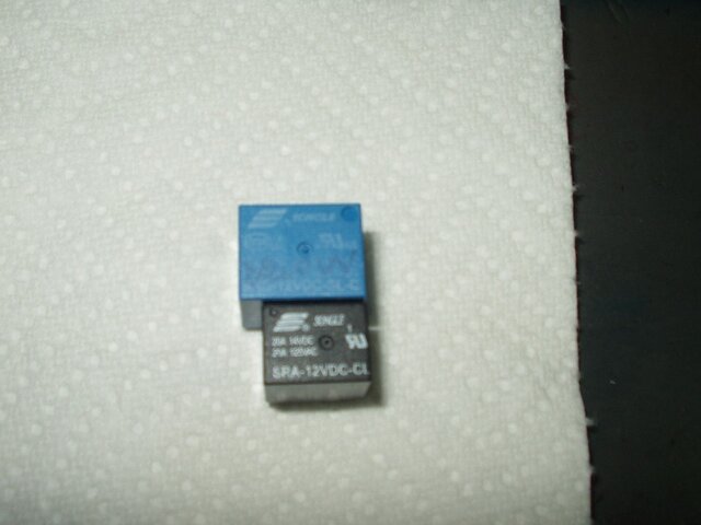
These relays aren't like the ones in you pic Magic. Here's one of each and along with the part numbers being different, the two are completely different size wise also. The wrong ones measure 15.5x12x13.5mm in size.

relays.jpg
 
Last edited:
Lone; If I understand correctly, you received ones measuring 15.5x12x13.5. You need ones that are 15x15x18, which are the measurements in the Ebay ad for the product you ordered. Is that right?
I can not be sure from the photo of the black ones that you received, but it may be possible that the ones you received will work electrically, but will not mount in the hole pattern. I have replaced relays in the past with a substitute when original size was not available, by running jumper wires between the relay lugs and the board holes, then using silicon rubber to hold down the relay in place.
Good Luck...
 
  • Like
Reactions: . Raine
migold yeah, I had thought of that too but the OEM style relays are still available and I'd rather not "rig" these if I don't have to. The vendor I was trying to get them from had a good price on 10 of them so that's why I was dealing with them. Several others have them but their prices are way higher. I guess I got what I paid for though, hey.
 
Thanks for the link, but, I don't order direct from china. Yeah, I know that most of the stuff comes from there but I just don't like dealing with them direct. That and if I did order from china those relays are .99 cents each shipped on fleabay.

At this point I"m not fully convinced that the relays are the problem as I've swapped out known working ones with ones that supposedly didn't work and it didn't work after that, meaning that the control circuit isn't turning it on. Trying to find out what controls that and maybe change one of those out to see if that fixes it.

All but one of the bad Vbox controllers I've got were taken out by lightning strikes. One (the first one I bought) got horked up because there was a loose nut behind the remote and I haven't made that mistake again since.

Ennywho, I haven't gotten any word back from the fleabay seller who can't read so right now the relay deal is on the back burner. I figure at least 2 of the 6 I already have should be good.

Thanks
 
The relays can be tested. How many leads come out the bottom of them? If there's only four, then two are the coil and the other two are the contacts. If there's more, then it probably has two sets of contacts.

With the relay out of circuit, the two coil wires should measure a relatively low resistance. If the contacts are NO, (normally open) the contacts will read open until power is supplied to the two coil pins, then the contacts should close and read zero ohms across them, (or very close).

A NC (normally closed) relay will read exactly opposite on the contact connections.

The voltage needed to supply to the coil should be listed on the side or top of the relay, probably 12VDC, but the voltage the contacts can handle is also usually there and a higher one, so make sure not to mess them up. The coil connections on the relay often have a resistor symbol between them engraved into the bottom of the relay too.

If you remove the relay from the circuit and it tests good, then most likely whatever drives the relay is shorted and keeping power supplied to the relay all of the time.

If the relay tests bad, well, then it's bad. If you remove the relay from the circuit, try powering up the unit with it removed and see what it does. If it still does what it's doing now, something else is screwy, if it doesn't, probably the relay or driving circuitry.
 
Yeah .Raine, I've checked the coils on the relays I've used and they read 320/420 ohms so the coils aren't open. I found a schematic which showed me the load carrying terminals. The relays have 5 connections on them and I did figure out how to test them with a 12v battery. They click when I put 12v on the coils and the terminals that are suppose to carry power also according to the meter they are closed so one would "assume" the contacts are good.

Ennywho, I got some help from KE4EST on this and he's sending me a controller chip to try, IF, I can get it soldered in that is? More uncharted territory for me and will be a crap shoot but at this point it really doesn't matter because they're already broken and not usable.

Thanks
 
  • Like
Reactions: . Raine and KE4EST
Ennywho, I got some help from KE4EST on this and he's sending me a controller chip to try, IF, I can get it soldered in that is? More uncharted territory for me and will be a crap shoot but at this point it really doesn't matter because they're already broken and not usable.

Thanks
Make it easy for yourself and buy a socket for that chip that KE4EST is sending. Solder that in and then just pop the chip into it to avoid heat damage. :)
 
  • Like
Reactions: . Raine
Maybe for the controller chip, solder in a ic socket for the chip and then you won't have to worry about putting too much heat to the chip when you're soldering it.

Make it real easy if you ever have to change it in the future too and they're cheap. I'd post up a link but I'm on my phone and it's a real pita on it.

Ah, I'm too slow typing! FTA4PA beat me to it! :)
 
  • Like
Reactions: FTA4PA
Ha, I beat both y'all. :D
I already have a socket with the chip packaged up. ;)
There are some cases in high frequency circuits that a socket can introduce unwanted impedance and/or capacitance. In any other case, though I use sockets like mad. :D
 
Status
Please reply by conversation.

Users Who Are Viewing This Thread (Total: 0, Members: 0, Guests: 0)

Who Read This Thread (Total Members: 1)

Latest posts

Top