Wiring up my next project

Status
Please reply by conversation.
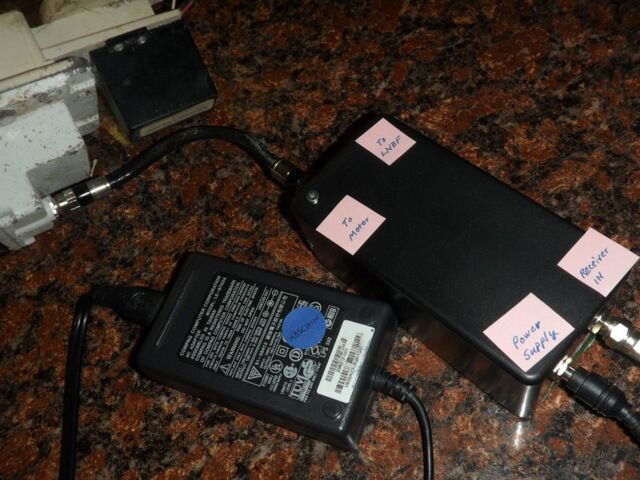
Still trying to externally power the HH-120 motor without breaking into the motor, I decided to try to copy qwert1515's device shown here

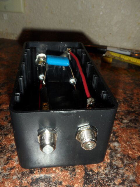
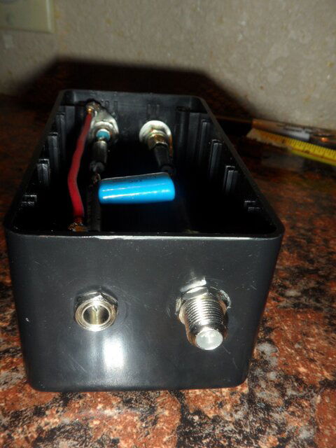
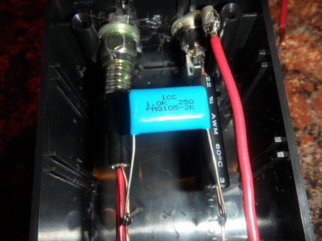
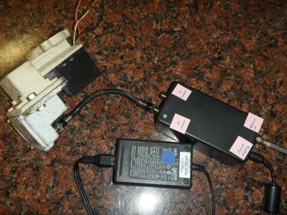
There is actually still a Radio Shack in operation the next town over. I made the 30 mile trip and bought a few items. Here is what I came up with:
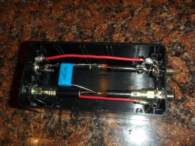
SAM_6181.JPG
SAM_6182.JPG
SAM_6183.JPG
SAM_6184.JPG
The main difference between qwert1515's device and mine is the capacitor. I was limited to what Radio Shack had on hand and the 1.0 uF K 250v is as close to the 155J 400v in the previously mentioned thread.

I'm not an electronics expert, but I think the capacitors would be similar enough in value to work?

The motor power input is for a laptop power source (19v). Pass through on the receiver to LNBF port worked fine. However, still couldn't get the motor to move with this external power source.
 
Wonder if a metal box would help too (shielding)?
Running two caps in parallel would make up for the capacitance difference for sure. 250-400v is kind of high, 100v tolarance should be fine but if all you have is the 250 it will work.
MIght have to mod my HH120 as wll to speed it up a bit... Might void the warrenty though (It's at least 8 years old!). :)
 
Getting back around to the HH-120 external power project...

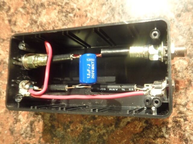
Per comments above, a 1.5J 250v capacitor replaced the 1.0K 250v capacitor.
SAM_6224.JPG
The 'device' still didn't externally power/operate the HH-120. While testing things out, I hooked up a LNB to the 19v powered side and the receiver display indicated that it 'saw' the LNB connected. An additional 1.5J capacitor clipped in did not operate the motor. Neither did two 1.5J with the original 1.0K.

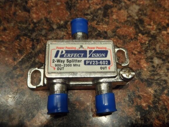
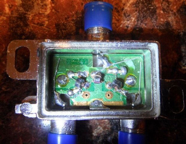
Moving on, I tried an alternate route. I had ordered a new splitter, in testing the splitter wasn't passing power as it should. Removed the cover off the back and had to solder a connection to get it to operate fully on all ports.
SAM_6205.JPG
SAM_6209.JPG
I also had a splitter on hand that worked more as a combiner. I confirmed power passing on the ports using an ohmmeter as well as connected to a 21v power inserter.
SAM_6219.JPG
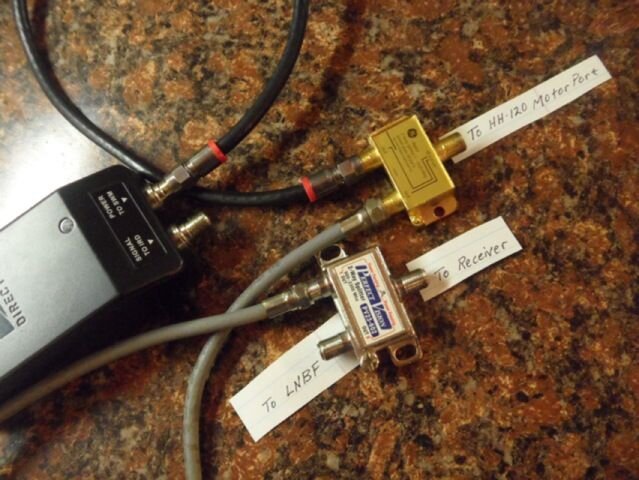
I tried the splitter and 'combiner' together and could operate the HH-120 (without the LNBF hooked up). The motor operated as it should. I connected the 21v power inserter in to the wiring, but left it unplugged. Wiring as shown below.
SAM_6218.JPG
Using this setup, without the LNBF attached and the power inserter unplugged, the motor would operate fine. Plugging in the 21v power inserter and the HH-120 motor would not move. As soon as the 21v power inserter was unplugged, the motor would operate again.

I tried the same splitter and combiner setup, except with power from the 19v computer power supply (used to power the 'device' in the first photo. Results were the same, without the external power inserted the motor operated fine. As soon as external power was inserted, the motor would not respond...

As it is, I'm perplexed... I'm thinking there is something simple that I'm missing, but don't know what. Any thoughts, suggestions or comments would be greatly appreciated.
 
Hi Jason,

In your alternative route, the golden splitter has a diode at the right side, which you connected (via splitter) to your receiver.
The left side has complete power pass, two ways.

As soon as you connect the external voltage to the golden splitter, with more voltage than your receiver gives, the diode gets completely blocked. Even the diseqc signal, superimposed on the receiver voltage, doesn't get through anymore: The amplitude doesn't get the voltage above 19 or 21 Volts. So the motor doesn't get any command.
That's why I wouldn't expect it to work, with this splitter.


With your original homemade splitter: I wonder what the problem is there. I wonder if the external power 'sucks in' the 22kHz? Have you tried other external power sources, that might work? Or maybe you need an extra coil to prevent leaking 22kHz to the external power?

Just trying to think about what might be the problem here....

greetz, A33
 
  • Like
Reactions: Jason S
Hi Jason,

In your alternative route, the golden splitter has a diode at the right side, which you connected (via splitter) to your receiver.
The left side has complete power pass, two ways.

As soon as you connect the external voltage to the golden splitter, with more voltage than your receiver gives, the diode gets completely blocked. Even the diseqc signal, superimposed on the receiver voltage, doesn't get through anymore: The amplitude doesn't get the voltage above 19 or 21 Volts. So the motor doesn't get any command.
That's why I wouldn't expect it to work, with this splitter.


With your original homemade splitter: I wonder what the problem is there. I wonder if the external power 'sucks in' the 22kHz? Have you tried other external power sources, that might work? Or maybe you need an extra coil to prevent leaking 22kHz to the external power?

Just trying to think about what might be the problem here....

greetz, A33

Hello and thank you, A33! Your reply is much appreciated...

Beginning with the alternative route - based on your description, it would seem to indicate that a lower voltage external power source (e.g., 16-17v) might allow the diseqc signal to pass? I presume this would be the case as long the diseqc signal was being passed from the receiver on a 18v vertical signal?

With the homemade splitter, I really have no idea what the problem may be. This would be my preferred route for external power to the motor. Have not tried other external power sources on it, mostly since I did not know that could be an issue. There are another 2 or 3 power supplies around here to experiment with to see if that may be the problem. With the splitter as built, the receiver will detect an LNB when installed on the external power side, so there is some function to it.

As for the extra coil to prevent leaking 22kHz to the external power source - What type of coil are you thinking?

I'm quite willing to experiment further with this and try to learn, even with my fledgling knowledge of electronics. Again, thank you for the insight.
 
Beginning with the alternative route - based on your description, it would seem to indicate that a lower voltage external power source (e.g., 16-17v) might allow the diseqc signal to pass? I presume this would be the case as long the diseqc signal was being passed from the receiver on a 18v vertical signal?

With the homemade splitter, I really have no idea what the problem may be.
Lower external voltage and your golden splitter: No solution, allas! Then the diode is in conducting mode, and your receiver is powering not only your motor, but also giving current to the external power supply. Not what you want, and it can cause trouble.
You really need a capacitor in the line that feeds the diseqc command from the receiver, to block the DC voltage!

With your homemade splitter: can you check if the 22kHz from the diseqc commands passes your splitter? Do you have a 22kHz switch, or a LNB that switches on 22kHz, to connect after your splitter? Then you can test if the 22kHz can reach the motor.
Better test that first, than experimenting with coils without knowing if that really is the problem. And I frankly don't know much about coils, apart from in what situation they might be usefull.
(And testing with other power sources: if easy to do, I would try it! If it works, then you know in what direction to search further. If it doesn't work, however, you don't know much more....)

Btw, you wrote your receiver can 'see' a LNB when connected to the motor-port of your splitter? How did you test that? What test-construction, with or without the external power, what reading on your receiver?

Greetz,
A33
 
Again, thank you A33.

Lower external voltage and your golden splitter: No solution, allas! Then the diode is in conducting mode, and your receiver is powering not only your motor, but also giving current to the external power supply. Not what you want, and it can cause trouble.
You really need a capacitor in the line that feeds the diseqc command from the receiver, to block the DC voltage!
No, don't want the receiver to power the power supply... It looks like the splitter route is out.

With your homemade splitter: can you check if the 22kHz from the diseqc commands passes your splitter? Do you have a 22kHz switch, or a LNB that switches on 22kHz, to connect after your splitter? Then you can test if the 22kHz can reach the motor.
That is a great idea! I have both, 22kHz switches and a universal LNBF to use for testing.

Better test that first, than experimenting with coils without knowing if that really is the problem. And I frankly don't know much about coils, apart from in what situation they might be usefull.(And testing with other power sources: if easy to do, I would try it! If it works, then you know in what direction to search further. If it doesn't work, however, you don't know much more....)
I'll test next with different power supplies and add in a 22kHz test.

Btw, you wrote your receiver can 'see' a LNB when connected to the motor-port of your splitter? How did you test that? What test-construction, with or without the external power, what reading on your receiver?
Attached are a couple of photos with the C-band LNB used and how it was configured for the test using a 19v computer power supply.
SAM_6227.JPG SAM_6226.JPG
Without power from the power supply, the receiver showed Intensity at 36% and Quality at 5% - as it normally would without a LNB(F) installed. Applying power from the power supply to the C-band LNB, the receiver shows I at 45% and Q at 5% - as it would with a functioning LNB(F) installed. This first test was when the 1.0K 250v capacitor was installed.

The same test and same results using the LNBF installed on the dish/motor I'm trying to externally power. A 1.5J 250v capacitor in the splitter for this test. However, I only had the LNBF powered long enough to verify detection by the receiver (i.e., go from I/Q of 35%-5% to 45%-5%). I cannot say at this time if it would've locked a transponder since it was only powered long enough to show a connected LNBF and then power was removed.

Looks like some more tests are in order...
 
  • Like
Reactions: Titanium
The splitters that I have used were Perfect10 OEM, non diode steered, all port power passing. I will dig through a few boxes and see if I can find one and post up the part number.
The part number for such would be very handy to have and much appreciated!

It can be a bit frustrating to purchase an "all-port power passing" splitter then test it to find out it isn't.
 
Completing this round of testing...

Homemade splitter: Trying another 19v computer power supply and still no motor movement. Thinking that AC from the computer power supply may be interfering, I tried an 18v Cordless drill battery connected with alligator clips to the splitter and no motor movement.

For the 22khz test, I used a cheap satellite meter which also shows the 22khz tone. I verified the meter still worked by installing it inline from the receiver with an LNB at the end. To run the test, moved the cable with the satellite meter to the 'motor' side of the splitter. With power from a computer power supply, the meter did not indicate a 22khz tone. Additional capacitors of the same same value, clipped in, did not change the results.

Also, as another test, I tried a four-port Diseqc switch on the 'motor' side of the splitter with the LNB connected to one of the ports. This test included various power supplies. The results showed that the Diseqc switch was not switching and the LNB attached inline was not 'detected' by the receiver.

So far, it seems the capacitors used thus far are not passing the 22khz tone.
 
Sorry, been on hospital duty this week and only in the shop for a few hours working on orders. Will be able to check for the app non-diode steered splitter next week.
Definitely understandable. There's no big hurry here... I've been tied up myself and this project proceeds as time allows.
 
So far, it seems the capacitors used thus far are not passing the 22khz tone.

Well, the capacitor will be passing the 22kHz, I guess, but the power supplies immediately suck it in/level it away, I think. Your test results suggest that to me.

I think it will be testing time for coils, now;).

I saw a link on a German forum tonight, which clearly shows a coil in the diagram of the Spaun combiner for DC (FSW5 / FSW30F ): http://spaun.de/pdf/pages/edition_14_de_96.pdf .
A coil functions as a resistor for high frequencies, while passing the DC. That way, the 22kHz from diseqc commands (and from 22kHz tone) can reach your motor connector again, I would think.
But that diagram is just theory....

And now for practice:
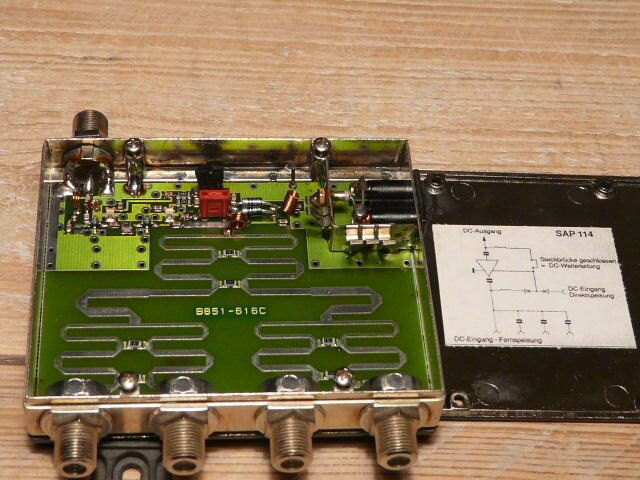
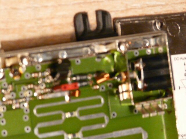
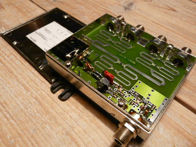
Also today (coincedence ;) !) I found on a fleemarket a sat-splitter with the possibility of adding external power: Polytron SAP114.
See the photographs.

P1060060.JPG P1060062.JPG P1060063.JPG

There are 3 coils in the splitter; the coil for the external DC-path is the biggest one, in the upper right of the first photograph.
This coil (from the DC-socket to the diode) has 12 windings (or how do you say?), the inner diameter is 2,5 mm, the copper(?) thread itself is about 0,5 mm diameter.
But I would think if you have or make something similar, the values wouldn't be all that critical.

Hope that I am right, and that this might be a break-through for your splitter-setup! :oldsmile


Greetz,
A33
 
  • Like
Reactions: Jason S
Well, the capacitor will be passing the 22kHz, I guess, but the power supplies immediately suck it in/level it away, I think. Your test results suggest that to me.

I think it will be testing time for coils, now;).

I saw a link on a German forum tonight, which clearly shows a coil in the diagram of the Spaun combiner for DC (FSW5 / FSW30F ): http://spaun.de/pdf/pages/edition_14_de_96.pdf .
A coil functions as a resistor for high frequencies, while passing the DC. That way, the 22kHz from diseqc commands (and from 22kHz tone) can reach your motor connector again, I would think.
But that diagram is just theory....

And now for practice:
Also today (coincedence ;) !) I found on a fleemarket a sat-splitter with the possibility of adding external power: Polytron SAP114.
See the photographs.

View attachment 110178 View attachment 110179 View attachment 110180

There are 3 coils in the splitter; the coil for the external DC-path is the biggest one, in the upper right of the first photograph.
This coil (from the DC-socket to the diode) has 12 windings (or how do you say?), the inner diameter is 2,5 mm, the copper(?) thread itself is about 0,5 mm diameter.
But I would think if you have or make something similar, the values wouldn't be all that critical.

Hope that I am right, and that this might be a break-through for your splitter-setup! :oldsmile


Greetz,
A33

Thank you again for the input and photos.

What you propose is definitely worth a try. If I don't already have something in my electronic parts, construction of the coil appears straightforward.

A couple of questions come to mind:

1) In your photos the coil appears to be bare copper wire. On the windings, each wrap of the wire looks to be tight to the next wrap. Do you think that the wire used in the coil is bare copper or has some form of coating like copper magnet wire (i.e., like lacquer or equivalent)?

2) To verify placement - It appears that the coil would be inserted between the external power supply and the capacitor on the 'motor' side of the splitter. Is that correct?
 
Did I read somewhere here that you did not want to mod the motor ala Pendragon for direct power injection?

I will try to find a link but there is a coating for coils. An Electrician gave me some when I was working on an old generator.
 
Last edited:
If you want to coat your coils:

Amazon product ASIN B000IC7ZQ2
Not what I used but similar. What I used was in a can with a brush like PVC glue comes in.
Go partially down the Amazon page and it will show you about 20 different types.
For small coils I would probably prefer to dip them. Some leftover rustoleum lacquer (nonmetallic color)
might do the same thing.
 
  • Like
Reactions: Jason S
Did I read somewhere here that you did not want to mod the motor ala Pendragon for direct power injection?
That's mostly correct, Fred. I'm trying to replicate the power inserting splitter that QWERT1515 posted [URL="http://www.satelliteguys.us/xen/posts/3452651/"]here[/URL]. I thought the homemade power injecting splitter would be an interesting project to complete my rewiring with the added possibility of saving a diseqc switch.

I'd like to run this experiment to its' conclusion. There are still options otherwise, like a Pendragon mod or just getting a 6' C-band polar mount and modify it, but I've come this far and it seems like it should be something simple...

As for the coil coating - Is coating considered desirable for operation or would it be considered a 'must'? If the coil was constructed from bare copper, would the wire need coating prior to coiling to prevent direct contact between each wrap of wire or just wind the wire and coat the coils to keep corrosion forming between each wrap?

BTW, Thanks for the links and input.
 
OK, I was not sure. I want to see this to it's conclusion too. Very interesting project.

They make pre-enameled wire for making coils also. The coating is required when wrapping motor armatures where the wires would touch. Or where your coils are comprised of multiple layers on top of each other, pre-enameled would be best. Maybe not needed in your project. Cant see the coil in the picture. Post enameling would probably be Ok for corrosion resistance or to prevent accidental shorting. Insulated wire would serve the same purpose.
For loose wound coils with no wraps touching, probably not required.

Here is a good document, they use a spacer when wrapping coils so the wraps don't touch.
Weed eater string, never thought of that!
http://www.arrl.org/files/file/Technology/tis/info/pdf/9708033.pdf
The coils they make are bigger than you need but the basic principles are the same.
 
Last edited:
OK, I was not sure. I want to see this to it's conclusion too. Very interesting project.
This is very much appreciated.

They make per-enameled wire for making coils also. The coating is required when wrapping motor armatures where the wires would touch. Maybe not needed in your project
Here is a good document, they use a spacer when wrapping coils so the wraps don't touch.
http://www.arrl.org/files/file/Technology/tis/info/pdf/9708033.pdf
The coils they make are bigger than you need but the basic principles are the same.

Thank you for the link. I'll be reading through this more tomorrow. My current thought is to take a length of solid copper RG-6 and remove the jacket. Then coil it to the specs A33 provided in his example and install in the splitter. The main variable I see at this point is coating before, after or none.
 
  • Like
Reactions: fred555
Status
Please reply by conversation.

Users Who Are Viewing This Thread (Total: 0, Members: 0, Guests: 0)

Who Read This Thread (Total Members: 4)

Top