Really don't know what's wrong

Status
Please reply by conversation.
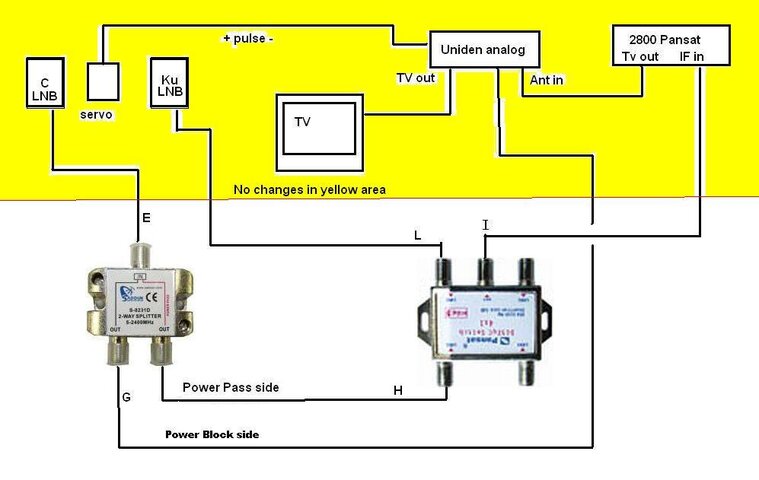
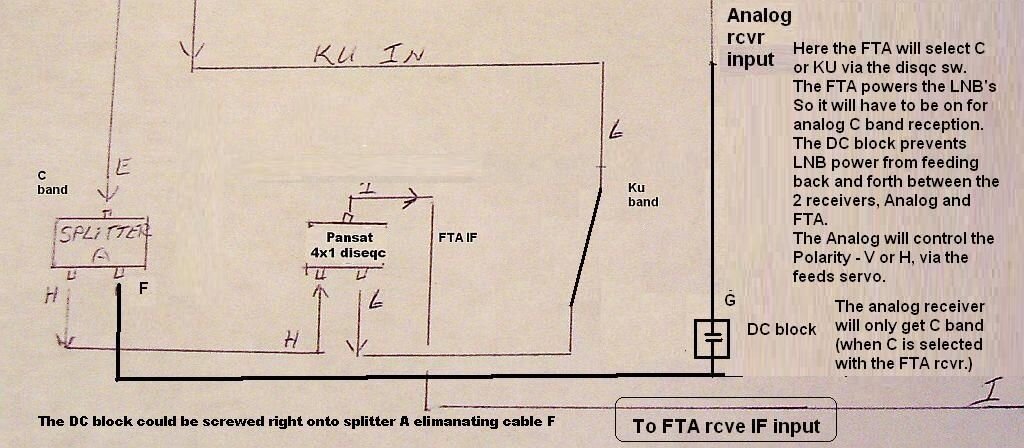
Are the, what you have labeled as splitters, just splitters, and not disqc or 22khz switches? Any ID numbers on them?
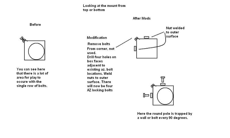
On the square az mount, are there only 2 bolts at the corner of the "box"?
If so, I/ve seen that before, and yes, troublesome, But then, I have to draw something for your mount. Quick and EZ fix I've done on a couple. Just requires a trip to the welding shop.
 
shankle, are, what you have labeled, splitters, just that, and not some other sort of switch? any numbers to ID them?
As for the mount, If that is just 2 AZ locking bolts on athe "corner" of that mount, I feel your pain. They do wobble excessively when loosened. BUT there is a Quick and EZ fix. I've done it on a few. Just requires a trip to the welding shop. See the attached.
Stanleyjohn, the blue box is servo for polarity.
 

Attachments

  • MOUNT.jpg
    MOUNT.jpg
    35.1 KB · Views: 140
Hi FaT Air,
Thank you for the informative msgs.
Now I'm just asking not questioning. I have a round item shown in a previous
post from an old Orbitron. It only needs one hole bored in it and welded to the existing mount. Is your method better, easier or less expensive? Or are both about the same?

The AZ locking bolts in the current mount are in the corner on the same side. Two of them.

Splitters -
splitter A is made in China and is only labeled with a number.
splitter B is a Pansat 4x1 diseqc switch super mini.
splitter C is made in China and is only labeled with a number.
splitter D a Radio Shack hybrid splitter combination.
 
The only concern I have about welding the orb mount to this one is, are you going to be able to keep everything straight? Because if an angle is introduced, it could cause pains in alignment.
Another way, Could the orb mount be modified to accept your present polar pivot piece?
Thank You for the splitter info, I will look over the wiring, but will have to leave for work soon, and may not be back here till around noon tomorrow. I think you'll be busy with that mount till then anyway.
 
Ok, I think 2 wires got interchnaged- see attached. Then another Question, How did you accomplish C - Ku selection with the analog receiver? I don't see it possible as wired.
 

Attachments

  • reply_000_0177.jpg
    reply_000_0177.jpg
    69.4 KB · Views: 120
Last edited:
Thank you FaT Air,
Back when I got the Uniden Receiver I had a 12' Paraclipse.
The mount wore out and I had to junk it. Of course it was only C-band.
I never used the Uniden to get ku Analog.
The next dish was the Orbitron which was C/KU.
That's when I got the 2 Norsat LNBs. Ku was never very good and the Q was always zero.

I guess you want me to change F and G on splitter D.
It's done.

Don't know when I can get to a welding shop. It might not be until Monday.
 
Till then, take a look at a simplified diagram that will work. It uses 2 less splitters, therefore we don't have the associated loss of signal. Which could be 10db or more per splitter. This alone could be a factor with the zero Q. The 2800 will select C-Ku via Disqc (analog on C band will be active while the FTA selects C band)
The Analog will select Polarity and Dish position.
The DC block will protect the receivers from each others LNB power. Without it, we could expect that something may get fried. (poof! - - soot! Don't want that.)
I searched for the DC block, and our fav(?), RS, doesn't carry them any longer. Maybe a local TV shop or cable company may have them. Otherwise, Sadoun Satellite Sale (888) 519-9595* has them - RF DC Voltage blocking coupler -listed on their website. What you think?
 

Attachments

  • saturday_reply_000_0177.JPG
    saturday_reply_000_0177.JPG
    85.2 KB · Views: 113
Hi FaT Air,
I have now dismantled the dish and sent the mount to the welding shop
as directed. They say I will have it by Monday.

This rewiring is way out of my pervue. Please be very precise with me and
I will try to follow your instructions. Only the lower half of my sketch is coming
through. If I am going to eliminate cable "F", how does any signal get to the
Uniden? You have shown cable "F" going into cable "G".
Could I ask that a new drawing be made with all the changes as you see them?
Right now I am a tad confused.

I looked on Sadouns site and could not find the "RF DC Voltage Blocking Coupler".
There is no search on the site to help me. I don't know what one looks like and
a picture of one would help.
Thanks much.
 
Good afternoon shankle.
Wire F can be eliminated because the DC block will screw directly onto the splitter, then G (the uniden input goes to the DC Block)

Better than that, would be to use a splitter made for sat IF (lnb output) splitting. One port passes DC, the other is DC blocked. S8231D Sadoun 2_way Satellite CATV splitter

If you can't locate a DC Block locally, I would order the Sadoun_2_Way_Satellite-Splitter instead of the DC Block. (same price)
I have marked the attached diagram as to how that would be connected.

Here's a direct link to the DC block to see what they look like.
RF Voltage blocking coupler s-g104 1-1000mhz
 

Attachments

  • complete_w_mod.JPG
    complete_w_mod.JPG
    215 KB · Views: 110
Hi FaT Air,
Thank you for the new sketch.
I would like to order the "sadoun_2_way_satellite-splitter".
Looked on the site and there are so many I have no idea which
one you mean.
Could you give me a # please?
 
Hi FaT Air,
The s-8231d sdoun/catv signal splitter has been ordered.
I figure about next Friday before it gets here.
Thank you.
 
Thanks for the nice sketch FaT Air.
Just two things for clarification:
1. +Pulse replaces my "A" and "B" right?

2. Can't read the fine print on the Pansat Diseqc switch. The one I have is the Pansat 4x1 Diseqc Switch Supermini. Is that one OK?
 
A is your actuator wires B is the red white and black to servo.
I see I didn't include the actuator wire (A), but, there are no changes there., nor to B
Only changes are made to the coax disqc switch and splitter connections.
 
One more problem.
This morning I went out to do a little maintenance on the dish while
I am waiting on the parts. The dish is setting on the ground and the
temperature is in the high 70s. So I thought while it's on the ground
is a good time to adjust the guy wires. Easy to reach and all that. So
I did. Did a little taping on the wires where they go into the button hook.
Couldn't paint as the surface of the metal was damp.

So about 11:00 o'clock I went back out to do some touchup painting
on the bolts and happened to look at the guy wires. It was now in the
high 90s to 100 degrees. The guy wires were loose.
What in the world am I going to do about that????????:eek:
 
What are the wires made of? In the heat, aluminum will expand more than steel.
Stainless Aircraft cable, probably, has the smallest coefficient of expansion.
Probably have to take up the slack in the heat of the day, and let them get tight when it cools.
How loose did they get, If a LOT, maybe my suggestion isn't that good, as it may pull on the dish excessively. If just a little, it probably is ok.
I'm in Northern Mn, so very rarely see that type of problem.

Your dissqc switch is fine, actually, just use the ports you are using now. The picture I used is from the pansat site, so thought it may be the same.
 
Thanks for answering Fat Air.
They loosened enough for the turnbuckles to sag.
The dish is aluminium and the cables are steel.
I also am afraid to tighten the turnbuckles in the heat of the
day and as you say warp the dish.
Would some type of plastic cord work. A heavy fishing line for ex:?
Or nylon cord or some such.
There is not that much pressure required to center the feedhorn
so it might work.

I was getting signal before I put them on. Maybe the button hook is not off
enough that I won't get any signal.
How do you handle your button hook?
 
Last edited:
I have a feeling that it's not the steel cables doing the majority of the expansion. Might be the aluminum dish. And the steel cable you now have will expand/contract less than nylon or plastic. But then again, you may try it and see how it works.
What do you think about putting springs on the outside end of the cables? Tighten up in the heat of the day/ let the springs get stretched a little in the cool of the night. Should work as long as the springs are stiff enough to hold the tension.
Another option is to have a sleeve on the center feed post with 3 arms made from some aluminum tubing. The sleeve is just snug, not tight, allowing it to slide up/dn during expansion/contraction.

The feed has to be centered, and here's why: At zenith the feed sags towards the bottom of dish. So the compensation is the polar angle. But, when we drive the dish off of zenith, the feed doesn't sag to the same point on the dish. It's now sagging off to the left or right of the center bottom of the dish. This would mean the azimuth would have to be tweaked one way for sats to the east, and the opposite way for sats to the west. And with varying temps the azimuth tweak would likely change as the feed sags more in hotter temps. Less when it's cooler.
FYI: whenever i use the term "drive the dish", this means move it with the actuator.

I don't do anything other than rotate my buttonhook 180 degrees every couple of years, just in case it is starting to sag. But my dish is HD steel and the button hook is also heavy wall steel. Like the guy that designed and marketed them said, "they are just about commercial quality". (USS, Theif River Falls, MN)
 

Attachments

  • myfarm.jpg
    myfarm.jpg
    80.5 KB · Views: 116
Status
Please reply by conversation.

AKA "Big ugly Birdview dish is a eye sore"

What's Up with Wealth TV?

Users Who Are Viewing This Thread (Total: 0, Members: 0, Guests: 0)

Who Read This Thread (Total Members: 3)

Latest posts

Top