Last edited:
More findings to make you jealous!! Birdview!
- Thread starter hank123
- Start date
- Latest activity Latest activity:
- Replies 30
- Views 4K
You are using an out of date browser. It may not display this or other websites correctly.
You should upgrade or use an alternative browser.
You should upgrade or use an alternative browser.
- Status
- Please reply by conversation.
Would you mind detailing your limit system? A schematic and the components you used. Took a minute to find the diodes. One of the drawbacks on the BV was no limit system. I was intending on mounting a large offset Ku on this mount. See the work you have done has renewed my interest in the projectYes, it is aluminum. I probably would have done more, but the kids were home for Christmas, so it was a good time to put up the dish. BTW, don't every turn down a free BirdView. Maybe a little small, but top quality stuff.
View attachment 119773 View attachment 119774 View attachment 119775 View attachment 119776 View attachment 119777 View attachment 119778
Would you mind detailing your limit system?
Sure. I got the limit switches off of ebay. I think they are these:
http://www.ebay.com/itm/281563458468?_trksid=p2055119.m1438.l2649&ssPageName=STRK:MEBIDX:IT
Yes, the diodes are the two things in TO-220 packages. I think they are 100 volt, 20 amp. Found them in my junk box, so that is what I used. 50 volt 3 amp would be about the minimum to use, but that is cutting it too close for me, 100 volt 5 amp would be better. The leads were too short to reach across the switch terminals, so I mounted them off to the side. Here is the schematic.
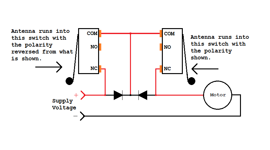
If the antenna keeps going into a limit switch, but then doesn't back out, the diode is connected backwards.
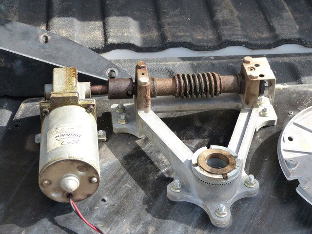
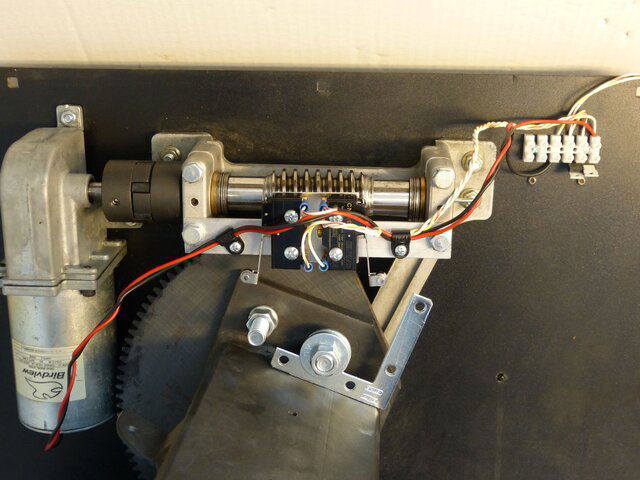
Mechanically the switches are mounted on a strip of aluminum across the two pillow blocks. It's not obvious from the photo, but there is a square piece of aluminum under the switches for the upper screw in each switch. Mainly to keep the switch from rotating if only one screw was used.
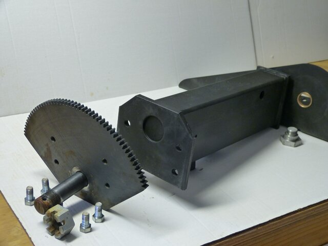
To mount the actuator paws, I reversed the direction of the sector gear mounting bolts. Ran longer bolts through the threaded holes in the sector gear, then the elevation axis, and a nut. Two large washers and a second nut hold a flat corner bracket in place to actuate the switch. The idea was to use washers to get the correct height and slide the bracket back and forth to set when the limit switch engages.
This didn't work out as well as I had hoped, A slightly bent bracket could miss the switch. So I added a block of aluminum to the bracket along with a springy piece of metal with an adjuster screw. Shown in post #16 above.
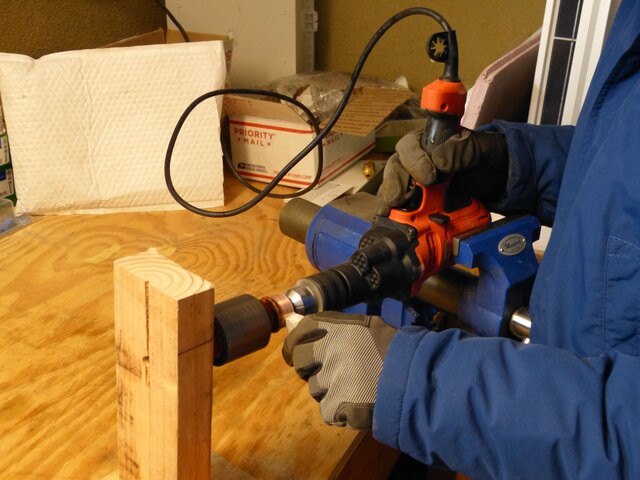
I love your makeshift lathe for turning down the commutator. Very ingenious. I will definitely use that.Yes, it is aluminum. I probably would have done more, but the kids were home for Christmas, so it was a good time to put up the dish. BTW, don't ever turn down a free BirdView. Maybe a little small, but top quality stuff.
View attachment 119773 View attachment 119774 View attachment 119775 View attachment 119776 View attachment 119777 View attachment 119778
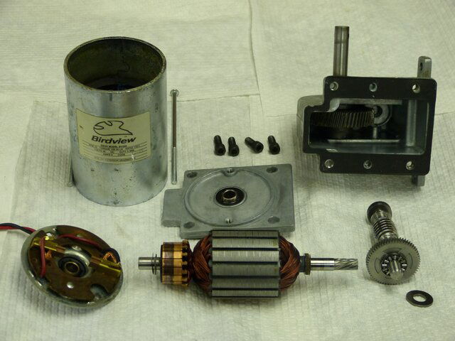
Yes, my "bench lathe" worked out pretty well. I used a fine grained seating stone to clean up the commutator.
I was hesitant at first about taking the motor apart. I'm glad I did because one of the brushes was completely stuck in its holder. The motor still worked , but with time arcing would have increased, damaging both the brush and the commutator.
I was hesitant at first about taking the motor apart. I'm glad I did because one of the brushes was completely stuck in its holder. The motor still worked , but with time arcing would have increased, damaging both the brush and the commutator.
You must have access to some neat stuff. I love that new shock absorbing coupler you put on the drive shaft. Thinking of ways to make it better is a lot of funYes, my "bench lathe" worked out pretty well. I used a fine grained seating stone to clean up the commutator.
I was hesitant at first about taking the motor apart. I'm glad I did because one of the brushes was completely stuck in its holder. The motor still worked , but with time arcing would have increased, damaging both the brush and the commutator.
Yes, I've had a lot of fun with this project and lots more to come! I got the Lovejoy coupling off of ebay:
http://www.ebay.com/itm/1-2-to-3-4-...bber-Spider-/201140868780?hash=item2ed4ee16ac
The old coupling was worn and getting some slop in it. Not bad but I'm trying to make this Birdview work without compromise. The new coupling is wider on the worm gear side than the shaft is long. I drilled a 1/2 inch hole in the rubber spider so I could shift the entire coupling toward the motor.
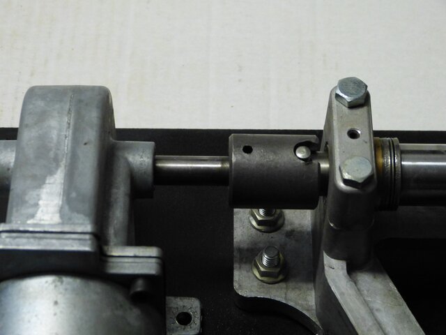
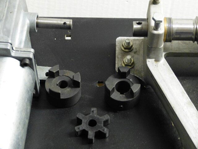
BTW, for anyone putting up a Birdview. Apparently there is an adjustment for the spacing between the sector and worm gears. I wasn't aware of this and my dish has a bit of slop in the drive. It only shows up when going past true south, gravity pulls the dish over about 1/2 degree because the teeth of the two gears don't mesh well.
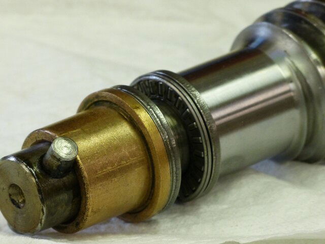
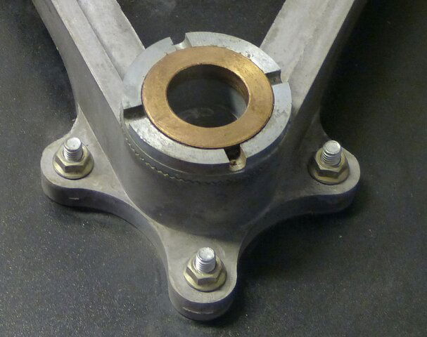
One of the upper elevation bearings is mounted with serrated teeth that allows the bearing to be inserted at any angle of rotation. I've been told that the bearing is slightly offset from center and this is how to adjust the meshing of the two gears. I haven't tried this yet, still trying to figure out how to do this without taking the whole dish down.
http://www.ebay.com/itm/1-2-to-3-4-...bber-Spider-/201140868780?hash=item2ed4ee16ac
The old coupling was worn and getting some slop in it. Not bad but I'm trying to make this Birdview work without compromise. The new coupling is wider on the worm gear side than the shaft is long. I drilled a 1/2 inch hole in the rubber spider so I could shift the entire coupling toward the motor.


BTW, for anyone putting up a Birdview. Apparently there is an adjustment for the spacing between the sector and worm gears. I wasn't aware of this and my dish has a bit of slop in the drive. It only shows up when going past true south, gravity pulls the dish over about 1/2 degree because the teeth of the two gears don't mesh well.
One of the upper elevation bearings is mounted with serrated teeth that allows the bearing to be inserted at any angle of rotation. I've been told that the bearing is slightly offset from center and this is how to adjust the meshing of the two gears. I haven't tried this yet, still trying to figure out how to do this without taking the whole dish down.

I have the older cast iron version. Not as friendly as yours. When mine was assembled they set the backlash and then drilled and pinned it. Not meant to be adjusted again.

I've heard that there was a cast iron version, but haven't seen one. Hopefully the backlash on yours is still correct.
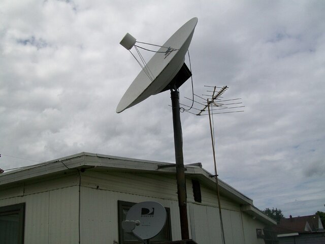
I will try to take a picture this weekend. She lives in a large mobile home. The pole is in the ground and also strapped to the side of the home. She said they used it from 1982-1992 when her husband died. It looks real rusty and rickety from the street.
The top of the pole is only 20 feet. It looks weak, but it survived the same 80 MPH winds that snapped my fence last year. The wife still will not allow me to take it down.
Attachments
- Status
- Please reply by conversation.
Similar threads
- Replies
- 16
- Views
- 1K
- Replies
- 2
- Views
- 415
- Replies
- 3
- Views
- 123
- Replies
- 1
- Views
- 137


