I Need Help, Installing a Titanium ASC1

Status
Please reply by conversation.

shanklej

SatelliteGuys Pro
Original poster
Apr 26, 2013
228
17
Ocala fl
7-12-2016
Got the Titanium pusher today. Just reading and trying to understand what to do.
Set the electric switch to 115.
The Titanium site has 4 manuals to download. I have no idea which
one to download.
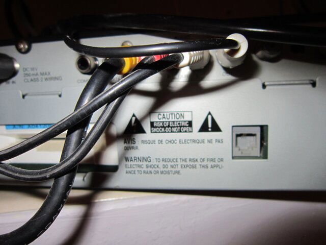
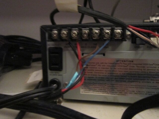
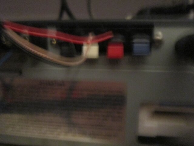
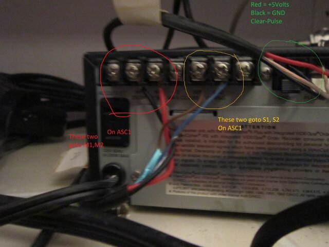
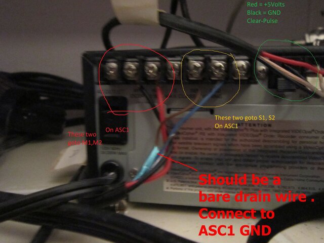
I have tried to take pictures of the Uniden SQ530 back panel but my
photography skills are sadly lacking. Hope they are of some value.
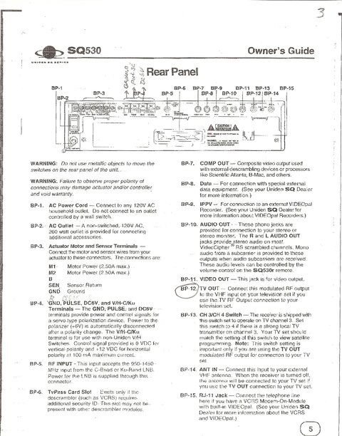
I also scanned the back panel from the Uniden sq530 manual.
I have 7 wires coming in from the Dish. The connectors on top of
the Uniden are a mystery to me.
I just knew this was going to be fun.......
Thanks for any help...
 

Attachments

  • scan0001.jpg
    scan0001.jpg
    558.5 KB · Views: 497
  • IMG_0310.JPG
    IMG_0310.JPG
    1.2 MB · Views: 408
  • IMG_0312.JPG
    IMG_0312.JPG
    1.7 MB · Views: 446
  • IMG_0313.JPG
    IMG_0313.JPG
    1.7 MB · Views: 426
  • IMG_0314.JPG
    IMG_0314.JPG
    1.5 MB · Views: 410
  • IMG_0315.JPG
    IMG_0315.JPG
    1.4 MB · Views: 405
Thanks for your help.
Got the manual.
Think I understand how to connect the wires shown on the left side of the
Uniden. (4 of them) Couldn't see how to connect the wires in the middle of
the Uniden. (3 of them) It's in another picture I have uploaded. The wires
on the right of the Uniden, I have no idea what to do with them. It's shown
in another picture I uploaded.
Which picture?
 
I think I have the 3 wires in the middle of the Uniden figured out.
I could not see them in the picture you uploaded. Screen wouldn't
move to the right.
The picture of the right side of the Uniden is img_310.
These I think are called RGB connectors. They are white
red and blue. I see no where to connector them on the Asc1.
 
Those are for left/right audio and video. Those will go to your receiver.
 
Plugged those into the receiver as directed.
Have not moved the dish from 55 and it is setting on Araing.
I can see the label for Araing and C band and others. After a few seconds
this goes off and then no picture on the tv.
 
The RCA cables that you removed from the old SQ530 were probably only for viewing the menu screen on your tv. These AV cables don't likely have a purpose anymore and just be disconnected and removed.

What brand and model of FTA DVBS2 receiver?

What type of AV connection between the receiver and the tv? HDMI? The TV input should be selected to view this input connection from the DVBS2 receiver.

Does the dish have C and KU LNBs or only C-band?

Is the ASC1 LNB voltage set to Fixed 18v to properly power the LNB?

How is the receiver coax connected to the ASC1? Did you remove the splitters and connect direct?

How are the LNB(s) connected to the ASC1?
 
Plugged those into the receiver as directed.
Have not moved the dish from 55 and it is setting on Araing.
I can see the label for Araing and C band and others. After a few seconds
this goes off and then no picture on the tv.
 
7-13-2016
1. I pulled the RGB cables out of the LinkBox 9000i.
2. The receiver is a new Linkbox 9000i.
3. I think you mean hdmi. It is connected to the Toshiba
on hdmi3
4. The lnbs are Chaparal C & KU
5. I am unable to follow the directions in the manual to
set the voltage to Fixed 18v.
6. There is a splitter from the dish for C band.
There is another splitter from the disk for KU.
Where would I connect these two wires to the Asc1?
7. Whatever connections I have made are wrong.
Thanks for anyhelp.
 
1. Good. The RCA cables are no longer needed.

2. Ok, Linkbox 9000i. Good receiver!

3. Keep the TV on HDMI input 3 to watch the programming from the 9000i receiver.

4. Ok, C and KU LNBs. Do you have a DiSEqC 1.0/1.1 or 22KHz 2x1 switch so the 9000i can select either C or KU LNB? If not, you need to purchase.

5. The step by step instructions for setting the ZLNB voltage in the ASC1 Operation Guide on page 10 are pretty clear. Let me know what isn't making sense.

To set the ASC1 LNB voltage to "Fixed on 18v": Enter the main menu and scroll down to LNB Type Set. Scroll down to Fixed on 18v and press OK. Scroll down to Save and press OK. Scroll down to Quit and press OK.

6. You no longer will use splitters, because you are disconnecting the old SQ530 analog receiver. The wiring example for C and KU LNB is on page 21 of the ASC1 manual. The C and KU LNBs will connect via coax cables to a DiSEqC or 22KHz 2x1 switch. The switch output f-fitting connects via coax to the ASC1 LNB f-fitting. The ASC1 receiver f-fitting is connected via coax to the 9000i receiver LNB IN f-fitting.

The satellite receiver will need to be programmed in the installation menu to select the correct switch port for each satellite. Example: if using a 22KHz 2x1 switch, connect the C-band LNB to 22KHz Off port and KU LNB to the 22KHz On port. In the 9000i select 55w satellite in the install menu and set the 22KHz switch setting to OFF (for KU satellites, set the 22KHz switch setting to ON).

Print a list of all C and KU satellites that you can see in the arc. Write a number beside each satellite name starting from the east or west (whatever you prefer). C and KU satellites in the same orbital position can share the same number assignment.

Now each satellite in the 9000i needs to have this satellite assignment number selected and the dish position saved. For example, if 55w is the most Eastern satellite and you decided to number the assignment #1, enter the 55w C-band satellite install menu on the 9000i and select an active transponder. Activate the motor type setting to DiSEqC 1.2 then select the motor position number to be 1. Drive the dish East or West using the 9000i to optimize the Signal Quality. Use the ASC1 to select the polarity of the transponder and slightly adjust the skew to optimize quality. Change the transponder on the 9000i to an active TP on the opposite polarity and select the other polarity on the ASC1 and adjust the skew slightly to optimize. Once optimized, move the ASC1 cursor back up to the Satellite Number (first line) and use the 9000i to "Save". By using the 9000i to save, the settings are synced between the 9000i and the ASC1! :)
 
This is in response to Titaniums previous message.
I finally got #5 to work.
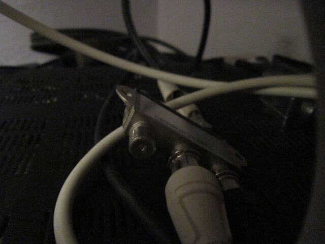
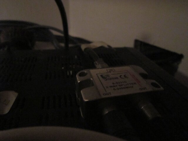
Will this diseqc1.0 work for #4? I have attached a picture of it.
Again I apologize for the bad photography.
The other stuff is going to take a while.
Thanks Titanium.
 

Attachments

  • IMG_0316.JPG
    IMG_0316.JPG
    1.5 MB · Views: 275
Yes, that is a DiSEqC switch.

The switch setting must be configured in the install menu for each active satellite to establish a signal path to the correct LNB.

Example: Connect the C-band LNB to port 1 and KU LNB to port 2. In each satellite set-up DiSEqC 1.0/1.1 menu needs to be set to Port 1 for C-band or Port 2 for KU.
 
7-14-2016
1. I have connected the output from the lnbs through the
disec 1.0 switch to #11 on the AsC1.
2. Then I connected a wire from the ASC1 #10 to the Linkbox #1
(if input).
3. Since I couldn't get anything on the screen I made the mistake
of moving the dish. Now I have no idea where I am at.
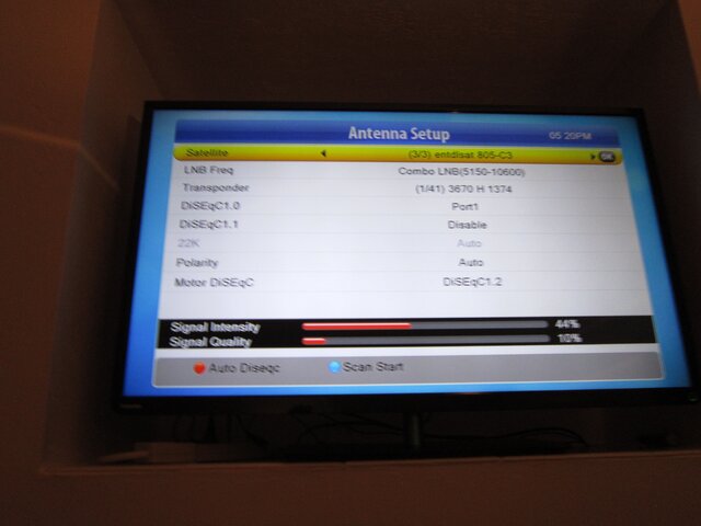
4. I have included a picture of how the antenna is set up
on the LinkBox 9000i.
I was able to set disexc1.0 to port 1 but see no way to
set ku to port 2.
5. I have put a check in 805 but the screen keeps showing
intelsat21 (58).
6. So how do I find 55 again so that I can reprogram that
satellite?
Thanks for your patience.
 

Attachments

  • IMG_0317.JPG
    IMG_0317.JPG
    1.1 MB · Views: 327
Now you need to configure your receiver. Like any satellite receiver, each line in the menu can be adjusted. Unless the correct selection is made for each menu item, no signals will be received. Maybe others more familiar with the 9000i can better assist you with setting up the receiver.

Here is a break down of the current install menu screen settings:

1. Satellite - As shown in the photo, the Satellite line is highlighted. To change to 55w C-band from 58w use the left or right navigation arrow.

2. Your C-band LNB is not a combo with dual LO frequency, it is a standard C-band LNB with LO 5150. Highlight the LNB line and use the left or right navigation arrow to set the LO to match the LNB - 5150.

3. Highlight Transponder and se the left or right navigation arrow to select an active transponder from the 55w C-band satellite.

4. The DiSEqC 1.0 setting is correct if the C-band LNB is connected to port 1 of the switch and KU LNB is connected to port 2.

5. DiSEqC 1.1 - not used

6. Use the left or right navigation arrow to set the 22KHz to OFF.

7. Polarity setting Auto is correct.

8. Motor DiSEqC is DiSEqC 1.2 and is set correct. Highlight Motor DiSEqC line and press Ok to enter the motor control menu. Use the East / West controls in the menu to position the dish until Signal Quality reading is found and optimized. Assign the motor number then save.
 
7-14-2016
Still having a lot of trouble. It's not the Linkbox or the ASC1. It's my lack of knowledge.

The dish is stopping a good 20" from the ground on the East side. I want to reset the
East limits and can't seem to figure out how to do it. I want my 000000 setting to be there.
Of course all my signal strengths are in the 40s instead of the 90s
I have followed the instructions to move the dish to get a higher quality signal and
have had no luck with it.
I am also confused where to do these changes with the Linkbox remote or the Asc1
remote.
I have been in the Diseqc1. settings and am getting nowhere.
 
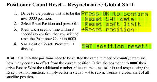
To reset the current position as counter 0000, See page 11 of the ASC1 Guide. Enter the System Reset menu and select Reset Position. Press OK twice. SAT position reset! will be displayed indicating that the current position is now 0000 reference.
Reset_Position_ASC1.jpg

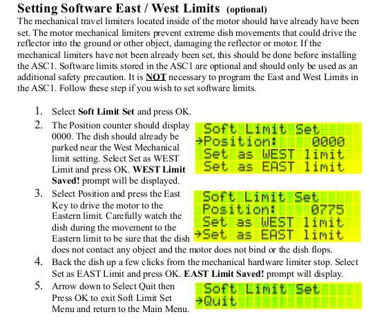
I usually don't set software limits and instead ALWAYS set the mechanical limits on the motor. The choice is yours if you also wish to set East and West software limits. See page 9 of the ASC1 Guide.
Set_Limits_ASC1.jpg

Use the 9000i DiSEqC 1.2 motor install menu to control the dish East/West position, assign a DiSEqC 1.2 motor number and "Save". This save issued by the receiver synchronizes the position and motor assignment to both the receiver and the ASC1. One saved, anytime the receiver selects a satellite, tunes a transponder or tunes a channel, the receiver will issue automatically issue a command to the ASC1 and the ASC1 remembers where the correct position is and instructs the motor to move to the position count number and remembers the polarity /skew setting for the selected satellite/transponder and instructs the servo to rotate the probe to the preset position. See the steps in post 14 above in this thread and also see page 13 of the ASC1 Guide.
 
Status
Please reply by conversation.

Chaparral Bullseye - servo & cap replacement

Hit the Jackpot

Users Who Are Viewing This Thread (Total: 0, Members: 0, Guests: 0)

Who Read This Thread (Total Members: 3)