Going to pick up a birdview this weekend, questions.

Status
Please reply by conversation.
Hmmm.....so, for...a former BV salesman who has now brought in yet ANOTHER BV owner to the club, and to this site, (one who has already shown innovation in making the BV's work for FTA even better also known as member "nicknjen")....we should also do this? I was selling BV in the 80's, and haven't been without one for more than a couple years!

I'm thinking we need a new club "constitution"......or "charter." Betcha the prez wouldn't mind!

I think your qualifications might just put you in the running for Prez, but don't forget about Phlatwound either. :)
 
I'm not eligible by the fact my hair would be expected to go gray during my term (if elected) because......I don't have enough left..and what IS STILL there is already gray from owning radio stations! (Presidents always age to gray when in office!) I keep adding to my thoughts here... actually, Nick is more of the "problem solver"....I'm the "Yes, you need a Birdview" spread-the-word kind-of guy. Probably cuz I write commercials all day!
 
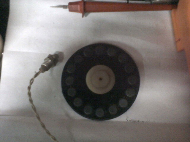
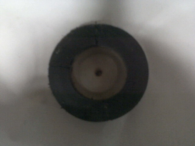
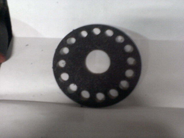
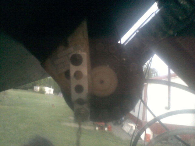
Whats going on guys are we having an election? So I had a few minutes today and played around with the magnets and switch. I used what I had lying around didn't get as many in the wheel as I wanted but its a start it will get me going. The wheel as about 3.75 inches and I only got 16 magnets in it, used my meter and checked it using my 18 volt drill battery to turn the motor. It seems to be dead on I don' have a Vbox or anything to really try it, it's on the way. 0509111925a(1).jpg0509111843.jpg0509111915.jpg0509111843.jpg0509112018.jpg0509111925a(1).jpg
pencil.png
The first picture is the original wheel.
 
I lied the original is in the second picture and I have no idea why the pictures are posted like that and some are double.
 
Do I understand you built the magnet wheel? Wow! You've jumped in quickly! Like others here have said, best to read every thread you can find with "birdview" listed in it, (use the search--it becomes your best friend when you're on a new project, believe me!) some of the latest (posts) being on how best to make a newer positioner box read pulses from your motorized mount. You may need more "resolution" than what that wheel can lend, but its not impossible to make the BV run with a few modifications. I'm not the expert on that one, but it is discussed at length of late on the board here. I've been lucky to work with a friend of mine on the project! (and more details come soon in their own thread, we hope.)
 
Last edited:
Well I know I don't want to be president. I've been president a whole bunch of times for this and that and mostly it is a pain in the posterior.

You know, I am kind of hoping that linuxman isn't giving up his exalted position. Even though a la Napoleon, he bestowed the presidency upon himself, based on his knowledge and experience, I couldn't argue the title.

I propose that I be nominated knight of the realm, or maybe friar or even gadfly in chief.


Actually, he didn't have a SAY in the matter. Anole and me BESTOWED the title on him. He woke up one day, and BAM, he had all this power. :D

Or something. :coffee

We MAY get together and choose the NEXT President too. We haven't talked about it yet.
 
Whats going on guys are we having an election? So I had a few minutes today and played around with the magnets and switch. I used what I had lying around didn't get as many in the wheel as I wanted but its a start it will get me going. The wheel as about 3.75 inches and I only got 16 magnets in it, used my meter and checked it using my 18 volt drill battery to turn the motor. It seems to be dead on I don' have a Vbox or anything to really try it, it's on the way.

What, If you don't have any luck with the reed switch as far as positioning this is what I did. I started out by getting a rotary encoder, this is just a little device that makes pulses when the shaft is rotated. These are used in a lot of industrial applications for motion control, I have used them for specialty equipment before. What they usually take 5 volts DC in and have a A and B signal out, Positive + and a ground -, and some have more leads but you wont use them.

My first attempt I bought a 20 count rotary encoder (so it will pulse 20 times when rotated one complete revolution) and coupled it to the shaft where the magnet wheel mounted. I just used a rubber hose and some zip ties to couple them together, being that there was basically no torsional resistance of the encoder. I then I ran 5 wires out to the dish, two wires to supply the motor and three for the encoder. One wire will supply 5 volts to the encoder connected to +, one is ground connected to -, and one is the signal back which can be connected to A or B or whatever the encoder calls the signal back, which sends the pluses back. The encoder when rotated sends through the signal wire a 5 volt pulse (which is called TTL, in this case +5v TTL) and if the encoder is rotated and you were looking at a scope you would see a 5 volt square wave.

Ok now that the wires were connected to the encoder I moved to the house where the Vbox was located. I connected the motor leads to the to the v box.

Now the Vbox just looks for a closure across the "sensor" leads on the back so putting 5 volts back in wouldn't work. I also needed a separate 5v power supply for the encoder so I had a cheap 6 volt power supply for something laying around (wall wart) and used that. I connected the + and - leads to the wire that went out to the + and - of the encoder. I still needed something to make the closure for the V box, so I decided to used a relay. I had a small "ice cube" relay from another industrial project laying around so decided to use that. I connected the signal wire from the encoder to the one side of the coil on the relay and the other side of the coil to the - ground lead (same lead that grounded the encoder. So now when the encoder is turned, it will open and close the contacts to the relay. Now to make the connections to make the closure for the V box. I connected leads from the "signal" terminals on the V box to a normally open "NO" set of contacts on the relay.

Tried the system out and BAM! it worked great! Now some things I have changed and want to change. I changed out the encoder from the first 20 count and went to a 48 count so I could get a "higher resolution" on movement. What this did is made it so the dish will move in a smaller degree of arc per each "count" seen on the V box. This enabled me to dial in on a bird better. I am toying on maybe going with a 80 count just to see how that works. Another change I want to make is take out the electromechanical "ice cube" relay and go with a solid state relay. I have been playing with that but with a solid state relay you need to have some sort of resistance on the closure to make it "make and break" and I have not gotten the fine balance of resistance yet.

Reason I went with the this over the reed switch is because I had the stuff available, and I wanted to be able to have a high resolution. I also didn't want to mess with the issues of making sure the switch was close enough to the magnets or other undesirable effects.


As for photos, I believe that Radio had taken some photos of the project, I have modified his birdview along with mine, you'll have to check one of his latest posts.

I will be soon starting a thread on the modifications I have done to my birdview, a materials list, photos, and maybe some measurements and drawings.

My next project is going to take the circuit board out of a small Ku dish mover and reverse engineer it to make it operate the birdview motor and get it so I can use USALS!! I just need to know how many pulses per degree of movement the small movers see... I am going to get a cheap one some time and take it apart and figure it out.. I will post what I find when I get around to that.

Short story long What, if you need any help with the above, let me know.
 
My next project is going to take the circuit board out of a small Ku dish mover and reverse engineer it to make it operate the birdview motor and get it so I can use USALS!! I just need to know how many pulses per degree of movement the small movers see... I am going to get a cheap one some time and take it apart and figure it out.. I will post what I find when I get around to that.


I may be able to help you with that, I THINK I have some unknown condition SG2100 circuit boards in a box that Brian sent me from SatAv awhile back, if you'd like.
 
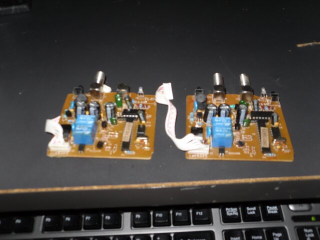
Nick is this what you need?
Yup. That is it. I am also going to get a complete one ordered. I think Sadoun has one pretty cheap in their bargen bin. What I want to do in theory is connect a separate 36 volt power supply and two separate higher current relays. The two current relays (blue ones on this board) will drive the other higher current relays. What I need the complete functioning box for is I want to just take the motor and connect a data logger to the encoder that is installed have it move the shaft say 10 degrees. And not 10 degrees of dish ark, just 10 degrees of rotational motion. I will count how many pulses the encoder gives back and figure out how many pulses there is per rotational degree (not arc degree). Then I will correlate that to the birdview.. match the pulses needed with an encoder needed and install that encoder on the BV. Connect the encoder and in theory it should work. Because the receiver adjusts for arc degrees per pulse because of the angle the dish sits, the rotational degrees around the pivot shaft of the dish will remain liner.
 
Yup. That is it. I am also going to get a complete one ordered. I think Sadoun has one pretty cheap in their bargen bin. What I want to do in theory is connect a separate 36 volt power supply and two separate higher current relays. The two current relays (blue ones on this board) will drive the other higher current relays. What I need the complete functioning box for is I want to just take the motor and connect a data logger to the encoder that is installed have it move the shaft say 10 degrees. And not 10 degrees of dish ark, just 10 degrees of rotational motion. I will count how many pulses the encoder gives back and figure out how many pulses there is per rotational degree (not arc degree). Then I will correlate that to the birdview.. match the pulses needed with an encoder needed and install that encoder on the BV. Connect the encoder and in theory it should work. Because the receiver adjusts for arc degrees per pulse because of the angle the dish sits, the rotational degrees around the pivot shaft of the dish will remain liner.

pssst. I have motors, too. ;)
 
Thanks nicknjen, I saw where everyone said to check out what you did but I searched and couldn't find anything. That sounds like the way to do it. Well I couldn't wait for my lnb to come in, could not have that nice big dish out here doing nothing. So I went ahead and hooked it up to see what I could get (I know all you guys would have done the same thing) lined it up at true south in my area is 77-78 well no c-band there. Then went inside with my drill battery (to move the dish) hooked the satellite finder up just a beeper stuck the battery on the motor wires I moved it west and beep so I stopped and did a scan to see what I had it was AMC 9 signal was about 72-75.I worked my way all the way up to AMC 18 same signal 72-75 so far so good. What kind of signals should I be looking for, before I go out and tweak? One more question the lnb on the dish is a echostar LNB-0950-IB the feed horn is made onto the scalar ring and it has a servo on it, and I could not find out any info on it. This is my first c-band so all this is new to me. Thanks Guys!!!!!!!!!!!!!!
 
That one only runs the older-style non-converted Birdview antennas. It relied on a potentiometer to talk to the box to relay positions back to the box instead of a reed-switch or the method that nicknjen has devised. However, as a box for testing BV motors, and simple moving back and forth completely manually, it could come in handy. It's also a very early one, as the joystick was for "fine" adjustment after dialing in the approximate numbers on the front panel. Later models went digital and talked via remote control, too.
 
It's also a very early one, as the joystick was for "fine" adjustment after dialing in the approximate numbers on the front panel.
Later models went digital and talked via remote control, too.
I picked one up a couple of years ago, but never looked twice at it.
Interesting to know there was more than one model. :)
 
Don't know what came before this, probably nothing, except the manual mounts.

After this model was the red LED model with digital numbers, connected usually by a DIN plug to the sensor and standard wire for the motor itself. Once that technology was "in place", they built upon it and incorporated the 00-99 positioner system (potentiometer driven) into the M-3 black and M-2 birdview-made receivers, getting down to one box with a 70mhz loop for the videocipher. All birdview-specific systems ran on the potentiometer system. The upgrades came to the reed-switch in the last few years of BV, so their hardware could continue to be sold (supporting the company) while they did not offer their own receiver. Had they not made the change to "high block" non-proprietary LNB's and the reed switch, the company would have died sooner no doubt.
 
Status
Please reply by conversation.

DSR905 Noob Needs Guidance.

General Instruments 550i Setup

Users Who Are Viewing This Thread (Total: 0, Members: 0, Guests: 0)

Who Read This Thread (Total Members: 1)