GOES 16 GRB downlink vs GVAR

Brett, I just came up with an idea.
It's more curiosity.
I'm wondering what your BBF error rate will do if you drop the signal quality to 42% there.
If you decide to do that please let me know the results.
 
It's locked and the SNR is 8.4 on the TBS Recorder screen. It looks fine from my distant perspective.

What happens in GRBStreamer? Does it report sync errors?
 
I would recommend optimizing the dish aim and can placement. I use EBSPro and the mobile app for Android. It sends (and speaks) the SNR periodically and is ideal for signal peaking. First I optimize the horizontal (east-west) and then bolt it down on the pole. Then I adjust the elevation. Finally I adjust the can distance from the dish. This is usually the most time consuming part because I have to adjust the can, climb down the ladder so I'm not blocking it, and then wait till the SNR steadies. I usually adjust it about 1/4 inch at a time and find the sweet spot.

If the above ^ doesn't help, then you might try duplicating my setup here as closely as possible. As I'm sure you are aware, the 90 degree combiner has 4 ports. I've got two of them connected to the can probes, one is connected to the sawbird+, and the other has the required terminator on it. My sawbird+ is battery powered. Its output connects to an sma to rg6 adapter and then 70 feet of rg6 cable going into my house through the wall. Finally the cable goes to a DC blocker which is connected to the DVB receiver.

The only amplifier in the system is the sawbird+. No additional amplifiers are necessary or advised.

The exposed metal parts of the sawbird are wrapped with black (non-conductive) electrical tape. Then the whole thing (battery, connecting cable, sawbird+ and combiner) is wrapped in aluminum foil to keep out any RF.
 
Thanks for the info Brett.
This has been a tough one.

I have tried everywhere from 45 1/2 - 46"
Due to the length of the can it was at 45 3/4" which is fine and the signal level of 8.4 dB C/N proves that.
+ that 45 1/2- 45 3/4" has been the sweet spot ever since I started this thing. To add the signal quality has not changed regardless of the position of the feed in the above area.

Yep, that's how I have the combiner hooked up. Sawbird is Batt powered as yours. Now the cable is only about 18" in length for the USB power battery, I feel this isn't an issue.
I find that the additional amp helps get a good signal level into the receiver. Maybe I don't need it but I have no DC blocker to put between the TBS and the sawbird. However, I did in a prior test with the Omnicom card just use the sawbird (because I can turn the coax power off on that card) with no change in signal quality. So I again feel that amp is not causing any issues here.

You seen how I shielded my sawbird as I posted that here many pages back (somewhere near P16 of this forum)

I know that if this was an interference issue (internal or external) I would be seeing some flux in the signal quality level. There is none it stays within 1 or 2% at the very most with the dish peaked, and I peak it.

Due to the error correction ability of this signal I should be getting some BBF's through even though the overall data would be lost, you proved that by running your system on the ragged edge out there with GOES 16.

I am now convinced that the TBS5927 receiver is Generic deaf. Even though it does see the BB Headers it drops the payload data. There's just a point here that you ask yourself "something just isn't right with this"
And I feel the Omnicom is the same, I will contact the guy in Russia and see if we can find some sort of solution to this issue. If I have any luck it will be with him.
I recall when you guys were just starting to mess with the DD cline card that it wouldn't work unless you installed an (I think) updated driver or firmware.
I feel the very same applies here, there is something with generic that the receiver can see it but it don't understand, so it discards the data it sees as not valid.

DVB-S2 signals are NOT this hard to receive, I had my goaround when I set up my NOAAPORT station. They're quite resilient to interference. They aren't if the receiver don't work for it.
If you still think that the receiver isn't the problem I will at my expense send the TBS to you and you can try it out. I almost guarantee that it will FAIL... unless the Win 10 driver is different then the BDA driver.

Don't take me wrong Brett, I take what you have told me seriously. But there's a point that the receiver can't be ignored anymore.
Exp with issues of DVB-S2 receivers and generic stream.
 
So the two significant differences between our systems are your different DVB receivers and the extra LNA in place of a DC blocker.

I will try either one of your DVB receivers here. I'll email you my mailing address. Meanwhile I would suggest replacing your extra LNA with the same DC blocker that I am using -- a Holland VBC-HR. They are widely available on eBay, Amazon and many other sources.

One way or another, we will figure out the issue with your GRB setup.
 
So the two significant differences between our systems are your different DVB receivers and the extra LNA in place of a DC blocker.
One last little thing to add, The coax I am using from the feed to the receiver is much shorter then yours and it's 50 ohm LMR240. This should make no difference but wanted to bring that up. Otherwise yes on the rest.

I will try either one of your DVB receivers here. I'll email you my mailing address. Meanwhile I would suggest replacing your extra LNA with the same DC blocker that I am using -- a Holland VBC-HR.
Just let me know, I recommend the TBS.
I should have asked you what that DC blocker was before, I'm glad I know and will get one. Thanks

With the feed eliminated it don't leave much now.
(Nodding head)
 
Hi, All--

After looking through all of the posts regarding the tortuous path of multiple levels of trials and error finding the right combination of hardware to produce a clean, error free GRB data stream I took a look at the 2nd half of the quest: software to display all of the imagery representing the various streaming data channels. My primary interest in downlinking the GRB signal is to produce and display the highest resolution GeoColor CONUS or CONUS full-disk earth images. Call me a pessimist, but I am concerned that the hardware may turn out to be the easiest nut to crack. I am exclusively a hardware guy; given enough pointers to the correct hardware path to follow I am pretty much capable of dealing with any pesky issues that come up.

However, solving most computer and software problems (for me, at least) is akin to emptying a bag of coral snakes one-by-one with my bare hands. Throughout all of my professional career I have had one or more techs on my team that were computer & software geeks. Any computer or software issues I encountered were generally solved by simply saying "Hey, Phil-- (or Tom or Bill or Sam or.....) Would you please take a look at this computer/software issue I am having? Thanks, Buddy!!" Now that I am retired (my blushing bride of 53 years says "retarded" instead of "retired") I am paying the price for always having a computer/software maven at my beck and call.

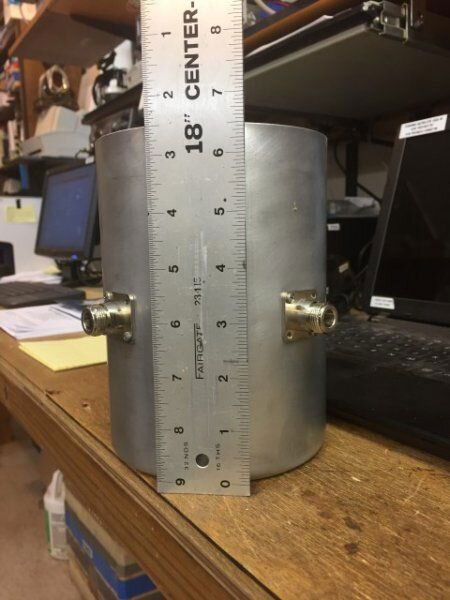
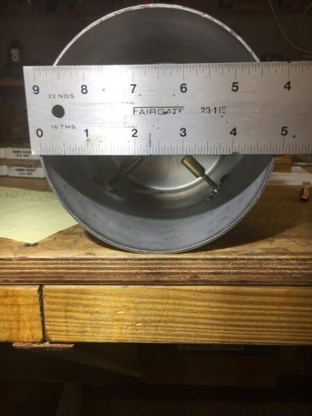
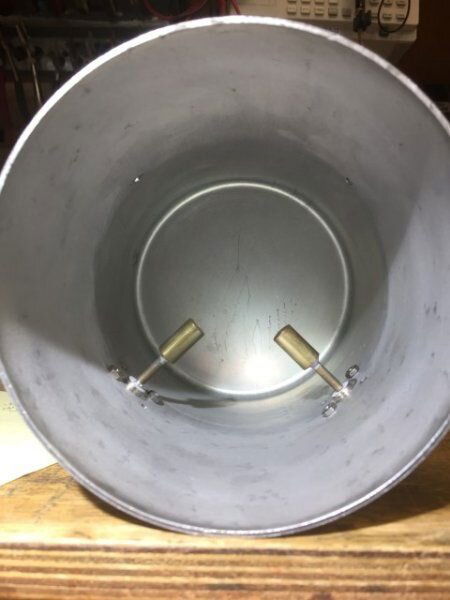
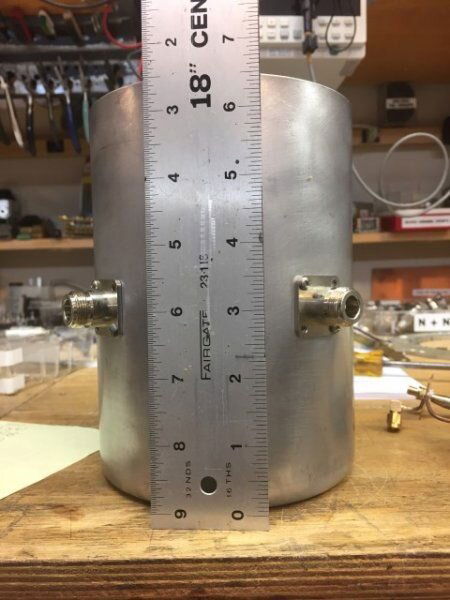
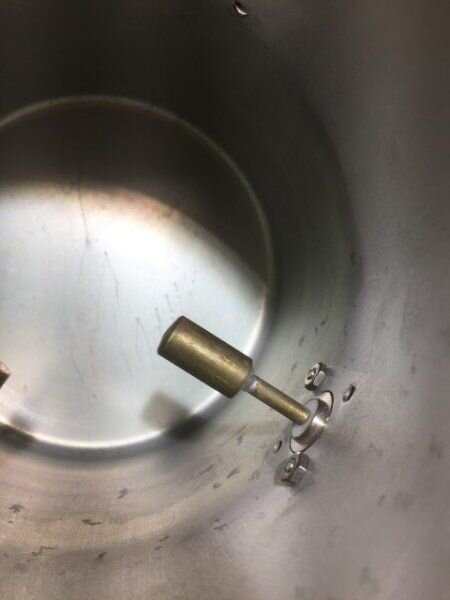
Speaking of hardware issues, I have a commercially made "cantenna" that I was told was originally designed for downlinking an L-band telemetry signal from an Inmarsat bird back in the late 80's. I had intended to change the length of the probes to match the 1/4? of the GRB signal at 1686.6 MHz. The can has two probes 90-deg apart and are connected to a 90-deg hybrid coupler to acquire the circular polarity 8PSK signal. Interestingly, the probes are located roughly in the middle of the can. Moreover, my VNA says that the near perfect SWR and Smith Chart display occurs at a frequency about 18 MHz lower than the length of the probes would indicate (if you assume that the probes are 1/4?. My guess is that the capacitance coupling between the probes and the wall of the can is lowering the resonant frequency response of the cantenna. Any thoughts on why the cantenna resonance occurs at a lower freq than the length of the probes might indicate? My next step is to fabricate 2 probes by cut-and-try that do tune the GRB frequency to acquire an excellent SWR and Smith Chart display on my VNA.

Mike Baker
Micanopy, FL
 
  • Like
Reactions: N6BY and hwboy4
After looking through all of the posts regarding the tortuous path of multiple levels of trials and error finding the right combination of hardware to produce a clean, error free GRB data stream I took a look at the 2nd half of the quest:....
He, he, he
This is another issue all to it's self. I have made my recommendation on here but it's far from the most convenient way.
It all depends how much control you are wanting to have over the datasets. Projection, histograms, maps and detail thereof.
This is where the cost could go high as this is a special item.
Others here are using programs to display the data but I have no idea to what level of detail is involved.
I do know that usually with the purchase of a workstaion (as it's called) for around $40,000 or more from the commercial guys out there you get that software with it.
I guess that in my case I might approach the commercial guys on this one depending on price, I would expect nothing less then a grand for a basic autoload display software?
But the software must be able to work with the NetCDF files.
On my GVAR system the files that the ingestor creates are special to the display software so they can't opened by other programs that I know of.
Lest see what anybody else has to offer as I have an big interest here as well.

I am exclusively a hardware guy; given enough pointers to the correct hardware path to follow I am pretty much capable of dealing with any pesky issues that come up.
Only problem with that connects with the paragraph below, The hardware here has a software connection that tends to have many to do with the issues that come up.
This is one of the drawbacks of building you're own worksation.

I do hope that you're familiar with Linux, that is due to CSPP Geo runs on CentOS or similar Linux.

Now that I am retired (my blushing bride of 53 years says "retarded" instead of "retired")
Ha,ha :oldlaugh

Speaking of hardware issues, I have a commercially made "cantenna" that I was told was originally designed for downlinking an L-band telemetry signal from an Inmarsat bird back in the late 80's.
Keep in mind that the probe length is not the only part of the waveguide that must be taken into account.
The can size (described many pages back) is very important to it's function of frequency.
Here a 5" can is what we want no less then 5". If it's bigger then 5" is should work too, though depends on how much bigger.
Also the probe distance from the back is a function of it's working frequency.
The designs here have focused on 1/4 wave from the back of the can (typ), My design has it a 1/2 wave from the back.

Any thoughts on why the cantenna resonance occurs at a lower freq than the length of the probes might indicate?
There are many factors that can affect the resonance of the cantenna, what you described is a good point. The probe's dia has an affect on that as well.
I will say Mike you go much farther then most of us here with that as the dimensions from the calculator is close enough for me considering this is only a RX system.

Otherwise go for it, try and see. It would seem that the feed you have may very well work and along with the patch antenna.
 
One last little thing to add, The coax I am using from the feed to the receiver is much shorter then yours and it's 50 ohm LMR240. This should make no difference but wanted to bring that up. Otherwise yes on the rest.
Just let me know, I recommend the TBS.
...
I agree -- the coax is not suspect here.

And the TBS would be the best for me to try. Since its USB, I will be able to try it with both Windows 7 box and my Windows 10 laptop.

...
However, solving most computer and software problems (for me, at least) is akin to emptying a bag of coral snakes one-by-one with my bare hands. ...
Thats OK because I am a software geek and I can juggle those software snakes with my hands behind my back, blindfolded, and upside down. :) Hardware is my weak area, but I did manage to duplicate 'KWX's known good setup and get it working.

Anyway, I can help with any software problems you may encounter.


...
Speaking of hardware issues, I have a commercially made "cantenna" that I was told was originally designed for downlinking an L-band telemetry signal from an Inmarsat bird back in the late 80's. I had intended to change the length of the probes to match the 1/4? of the GRB signal at 1686.6 MHz. The can has two probes 90-deg apart and are connected to a 90-deg hybrid coupler to acquire the circular polarity 8PSK signal. Interestingly, the probes are located roughly in the middle of the can. Moreover, my VNA says that the near perfect SWR and Smith Chart display occurs at a frequency about 18 MHz lower than the length of the probes would indicate (if you assume that the probes are 1/4?. My guess is that the capacitance coupling between the probes and the wall of the can is lowering the resonant frequency response of the cantenna. Any thoughts on why the cantenna resonance occurs at a lower freq than the length of the probes might indicate? My next step is to fabricate 2 probes by cut-and-try that do tune the GRB frequency to acquire an excellent SWR and Smith Chart display on my VNA....
I don't know why the resonance is at a lower frequency. I'll be interested in seeing your final result. My cantenna uses the dimensions at this post: GOES 16 GRB downlink vs GVAR
However, the inside diameter of the can is 122 mm, (not 127). I used the closest can available (which was discovered by KWX to be a 'Cien en Boca' cookie can.)
 
Last edited:
*********************************************

Hi--
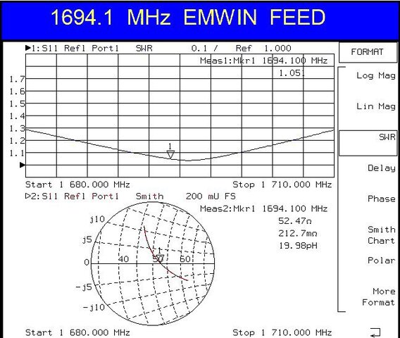
I am wondering what results some of these several varietions of home-brew cantennas would show when looked at with a high-quality VNA (vector network analyzer). I have an Hewlett Packard 8714ES with several extra optional functions. I have had it checked and calibrated by an outfit over at Cape Canaveral who services and calibrates lab-grade RF test equipment for NASA. I have a couple of reference standards for confirming the accuracy of its more critical measurements. Generally I examine feeds for SWR, 50 ohm impedance, capacitive and inductive reactance as measured on a Smith Chart display.

Now, having said all that, as you know, just because a feed looks good on the VNA does not mean that it properly illuminates and matches the f/D of the dish it is mounted on. W1GHZ, Paul Wade, has published a monumental treatise on a variety of microwave feeds, including the cantenna style.

See: Table of Contents - W1GHZ Microwave Antenna Book ONLINE Specifically, 6.3.1 and especially 6.3.2 for info on adding a choke flange to the cantenna.

If someone sends me a cantenna to test I can return it along with a copy of my standard SWR and Smith Chart display such as the one attached here.

Mike Baker
Micanopy, FL
 

Attachments

  • 1694.1 EMWIN Feed.jpg
    1694.1 EMWIN Feed.jpg
    93.3 KB · Views: 329
... My primary interest in downlinking the GRB signal is to produce and display the highest resolution GeoColor CONUS or CONUS full-disk earth images.

...
I am wondering what results some of these several varietions of home-brew cantennas would show when looked at with a high-quality VNA (vector network analyzer). I have an Hewlett Packard 8714ES with several extra optional functions. I have had it checked and calibrated by an outfit over at Cape Canaveral who services and calibrates lab-grade RF test equipment for NASA. I have a couple of reference standards for confirming the accuracy of its more critical measurements. Generally I examine feeds for SWR, 50 ohm impedance, capacitive and inductive reactance as measured on a Smith Chart display.

Now, having said all that, as you know, just because a feed looks good on the VNA does not mean that it properly illuminates and matches the f/D of the dish it is mounted on. W1GHZ, Paul Wade, has published a monumental treatise on a variety of microwave feeds, including the cantenna style....
NOAA is sending different data in RHCP and LHCP at the same time and the same frequency. In order to generate GeoColor you need to be able to receive both polarities of the GRB signals simultaneously. You need channel 2 from LHCP and two other channels from the RHCP signal.

So the cantenna is fine for black and white images or getting your system up and running quickly, but it is not the final goal (for me at least).

'KWX' tried a cantenna with 4 probes for simultaneous reception but it didn't work. Is there a way to receive both RHCP and LHCP at the same time with a can antenna? I don't know. If not then our choices are 1) a septum feed, 2) a patch antenna with 2 feed points, or 3) a dual helical coil feed.

The other consideration besides SNR and proper dish illumination is the cross polarity isolation.

I have built a septum feed. Last time I tried it was with GOES-16 at 75W. Today I plan to try it again with GOES-17 at 89.5W.
 
especially 6.3.2 for info on adding a choke flange to the cantenna.
I have read a chunk of that and my feed has a choke ring. In some of the simulations and tests he did show results with a choke ring over the coffee can feed. It's of no surprise that the C band feeds use this. Recently I have been experimenting with different sizes.
But all that's on hold until I can get some kind of data off my link.

If someone sends me a cantenna to test I can return it along with a copy of my standard SWR and Smith Chart display
I'll keep that in mind

So the cantenna is fine for black and white images or getting your system up and running quickly
And lower cost..

Is there a way to receive both RHCP and LHCP at the same time with a can antenna?
I came up with an idea that split the 2 probes that had 2 combiners with both streams but haven't tried it yet as the setup here is having said issues.
The setpum feed has proven to work, but is a bit tricky to fabricate/build.

I have built a septum feed. Last time I tried it was with GOES-16 at 75W. Today I plan to try it again with GOES-17 at 89.5W.
It worked good for you Brett, You should have good luck with it on GOES S.
My round one went to the scrapper. It didn't work at all.
I may approach this again but will use the square style with a choke ring.
When I get there....
Also I got a reply back from Omnicom, There having the tech look into it.
 
..
I have built a septum feed. Last time I tried it was with GOES-16 at 75W. Today I plan to try it again with GOES-17 at 89.5W.
Good news. I just finished testing the septum feed with GOES-17 at 89.5W. I got an SNR of 10.0 !! Thats about 2 dB better than the cookie can's 8.0.

So tonight I'm going to re-aim my dish to GOES-16 75W and try processing it.....

Septum.jpg
 
After a bit of tweaking I got GOES-17 up to 10.2 dB

Then I moved the dish to GOES-16 (75W) and got 9.8 dB. My septum feed works very well!

What seemed to really help was attaching the Sawbird+ directly to the septum with no cable in between. Also made my own bias-tee / DC blocker by gutting a TV splitter box and soldering in a 47 pf capacitor. It blocks the DC from the DVB card and has 5V on the other side of the capacitor going out to the sawbird+.
 
Some comments and observations:

A) It appears that a cantenna feed (if PROPERLY configured) will work for receiving both polarities from the GRB signal. I say this as I have seen a commercial cantenna feed for an L-Band downlink at a NASA facility at the Cape that had 4-probes and two 90-deg hybrid couplers feeding a pair of LNA's. I do not know the details for the specific L-Band channels but was told that they were 15 MHz wide high-data-rate channels that were adjacent to each other, and that one was LH and the other RH polarity to minimize any adjacent cross channel coupling effects. This was on a dish that was about 10-ft diameter.

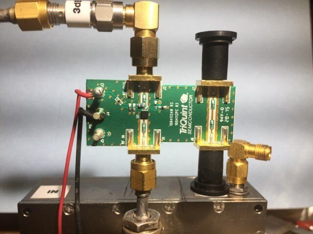
B) Regarding LNA's for GOES downlinks.....: I have been using an LNA made by TriQuint, Inc (now Quorvo, Inc) which has a NF of 0.39 and gain of 21.5 dB at GOES downlink frequencies. It is p/n TQP3M9037-PCB which is an evaluation PCB version available from parts distributors such as Mouser.com for around $65. The NF and gain I show here were the result of measurements made by a local friend who designs the latest bleeding-edge medical MRI machine circuitry for a major manufacturer who has a $30K noise figure meter on his workbench. A photo of this LNA is attached.

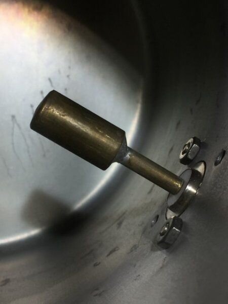
Also attached are some photos of a commercially made cantenna made for a NOAA L-Band Met-Sat (NOAA-18) downlink at
around 1702 MHz. This is the cantenna I described that has the probes cloce to the center of the waveguide. Note also that the probes are SHORTER than 1/4 ?. When removed from the cantenna they are resonant at a freq around 10% higher than when they are mounted inside the cantenna. I am thinking that this is because of the capacitive coupling between the probes and the wall of the waveguide. This tells me that several of the diagram guides I have seen listing the probe dimensions as 1/4? are probably wrong. My HP 8714 ES VNA seems to confirm this as my somewhat shorter than 1/4? homebrew probes do resonate at 1686.6 MHz.

Mike Baker
Micanopy, FL
 

Attachments

  • IMG_1770 (Small).JPG
    IMG_1770 (Small).JPG
    42.4 KB · Views: 342
  • IMG_1771 (Small).JPG
    IMG_1771 (Small).JPG
    38.3 KB · Views: 358
  • IMG_1772 (Small).JPG
    IMG_1772 (Small).JPG
    32 KB · Views: 317
  • IMG_1773 (Small).JPG
    IMG_1773 (Small).JPG
    44.9 KB · Views: 348
  • IMG_1774 (Small).JPG
    IMG_1774 (Small).JPG
    23.3 KB · Views: 346
  • IMG_1775 (Small).JPG
    IMG_1775 (Small).JPG
    24.8 KB · Views: 354
  • IMG_1778 (Small).JPG
    IMG_1778 (Small).JPG
    49.7 KB · Views: 342
...
B) Regarding LNA's for GOES downlinks.....: I have been using an LNA made by TriQuint, Inc (now Quorvo, Inc) which has a NF of 0.39 and gain of 21.5 dB at GOES downlink frequencies. It is p/n TQP3M9037-PCB which is an evaluation PCB version available from parts distributors such as Mouser.com for around $65. The NF and gain I show here were the result of measurements made by a local friend who designs the latest bleeding-edge medical MRI machine circuitry for a major manufacturer who has a $30K noise figure meter on his workbench. A photo of this LNA is attached....
Myself and several others are using an LNA / Saw filter combo unit made by Nooelec. Its called the SawBird+ and is specially designed for GOES GRB reception. It works very well. I can now use it (along with my Septum feed) to receive both GOES-16 and GOES-17. Its about $40.
 
Hi-- Regarding the Nooelec Sawbird+ LNA and integral bandpass filter....:

N6BY said: Myself and several others are using an LNA / Saw filter combo unit made by Nooelec. Its called the SawBird+ and is specially designed for GOES GRB reception. It works very well.
*****************

The Nooelec info on the Sawbird+ LNA with integral bandpass filter says:
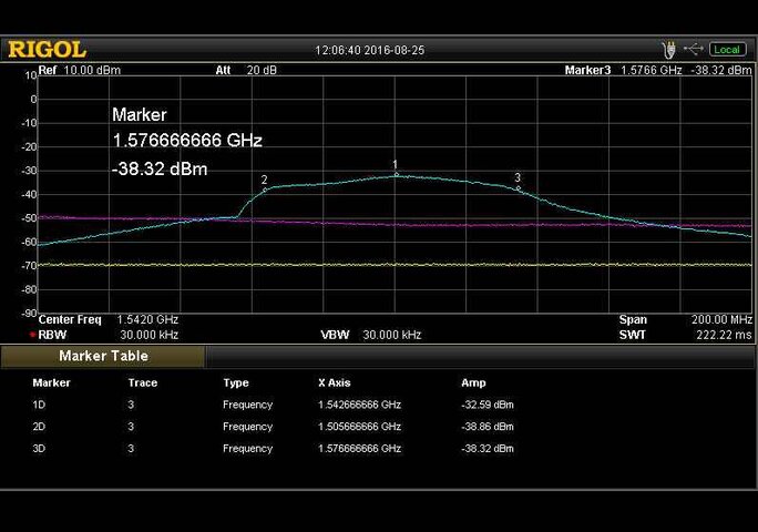
> "The center frequency of the module is 1.5420GHz with approximately 80MHz of bandwidth (-6dB rolloff). As such, it should be used for reception of frequencies between 1.50GHz-1.58GHz. The LNA is a dual-stage design with a very low noise figure of 1dB (nominal)." >
********************
The performance graph shown by Nooelec for their Sawbird+ (see attached) shows that its bandpass response is not suitable for GRB at 1686.6 MHz. An 80 MHz bandwidth centered on 1.542 GHz will result in very degraded performance at 1686.6 MHz no matter how good its noise figure is. You said that it is "specially designed for GOES GRB reception. Apparently I am not looking at the right version of the Sawbird+ ? I do not see a version that is specially designed for GOES GRB at 1686.6 MHz. What am I doing wrong...??

Mike Baker
***********
 

Attachments

  • Saw.jpg
    Saw.jpg
    44.6 KB · Views: 304
Hi-- Regarding the Nooelec Sawbird+ LNA and integral bandpass filter....:

N6BY said: Myself and several others are using an LNA / Saw filter combo unit made by Nooelec. Its called the SawBird+ and is specially designed for GOES GRB reception. It works very well.
*****************

The Nooelec info on the Sawbird+ LNA with integral bandpass filter says:
> "The center frequency of the module is 1.5420GHz with approximately 80MHz of bandwidth (-6dB rolloff). As such, it should be used for reception of frequencies between 1.50GHz-1.58GHz. The LNA is a dual-stage design with a very low noise figure of 1dB (nominal)." >
********************
The performance graph shown by Nooelec for their Sawbird+ (see attached) shows that its bandpass response is not suitable for GRB at 1686.6 MHz. An 80 MHz bandwidth centered on 1.542 GHz will result in very degraded performance at 1686.6 MHz no matter how good its noise figure is. You said that it is "specially designed for GOES GRB reception. Apparently I am not looking at the right version of the Sawbird+ ? I do not see a version that is specially designed for GOES GRB at 1686.6 MHz. What am I doing wrong...??

Mike Baker
***********
The unit on Nooelec's website that you are referring to website was designed for "Outernet" and other Inmarsat frequencies. The "Sawbird+" we are using is not listed on the website yet, but is specially designed for GOES reception at the correct frequency. To obtain one you have to email Nooelec and request that they send you an invoice for a Sawbird+.
 
Top