OTHER C Band Orthomode Feed. How do you switch LNB's?

arlo

SatelliteGuys Pro
Original poster
Dec 4, 2016
1,360
923
North Eastern
Like the subject says. Wondering how it's usually done. I see tek has a 13/18 volt switch. I just refuse to buy anything from him.
Other searches come up a bit blank. It might be covered in the archives here but that's some deep searching.
In the interim. Although it might not be kosher. I was messing around and found my own solution w/o buying more stuff.

I use a 8X1 diseqc switch to select between C and Ku on my mio. For blind scans of unknown sats. when initially setting them up.
I edited the satellites.xml file to make a dummy that I could set to not move the dish.
Also a few years ago I found that I needed to nudge the dish a few clicks on 131W for different tp's.
These work:

<sat name="Test C-band Transponders" flags="1" position="-1775">

And for the dish 'nudge'....

<sat name="131.0W C-band AMC 11" flags="1" position="-1311">

<sat name="131.0W C-band AMC 11 *" flags="1" position="-
1312">

Names edited so I know what I'm on. And numbers in red exclusive so I can set my dish mover memory slot.

So. It looks like it will work. I'm getting my 'guns loaded'. More on that.
Make duplicate entries in the xml.
Signify H, V tp's by appending, let's say....
<sat name="131.0W H C-band AMC 11" flags="1" position="-1311">
include only horiz. tp's in it and add new blind scanned findings.
<sat name="131.0W
V C-band AMC 11" flags="1" position="-1313">
only vert. tp's in it. same for new scans.

Follow me? In Tuner setup set Port 1 for C band and voltage at 18 volts for the horiz. lnb.
Port 2 for C band, 18 volts for the vert. lnb.
And Port 3 for my sidecar ku lnbf.
Only 1 coax needs to be added to get everything down one wire to the house.

Any suggestions? A better and reliable way?

An old buddy/plumber just bought the home of the CATV owner before being bought out by the big guys.
He called me up and asked me if I wanted to look through the old stuff before he hauled it out for junk.
Boxes and boxes of new tubes. Mostly for RF amps. A mess of rectifier tubes.
And few few old boxes of dish components. Assorted Norsat lnbs. Need testing. Some look new. Others are crusty.
And a bunch of ortho feeds. I snagged a Harvard Scientific and CM. The rest are pretty crusty and weathered and pitted. Some scalars.
Tickled? Oh yeah.
Used my friends glass bead blaster. Looked up another one and he's going to powder coat them.
The plumber isn't in a big hurry to get rid of everything. But it will go.
 
Thanks Bri.
Already have most of my C band xml done. A bit. Not much work. No extra hardware or mods needed. And tested.
I have no 5G interference out here in the sticks. Hopefully I can snag a couple of Norsat's that work.
Knowing little but what's still bolted to my Chaparral polorotor C/ku feeds in "the bin".
Are specific flange gaskets really needed? I put Kapton tape on the feed flanges. Hoping it survives the powder oven.
 
Use a powered multi-switch with the paired ports modded to provide 18VDC to both of the C-band orthomode LNBs. Run the KU LNBF on an unmodded high band port. I remember some threads years ago with Anole, Magic Static and others regarding their ortho switching hardware.
That is the best and easiest set up that I use, A powered WNC 4x8 switch modded to 18 volts on the C-Band side and the Ku also. 10 foot unimesh brand new in the box six years ago with a Chaparral ortho and norsat 5 series LNB's and a 1.8 andrews with the original ortho and 2 Norsats on it. Works like a charm. And of course, your box moving the 10 footer!
 
I guess since it works I'd still be interested in finding the circuit mod. So far a search here didn't lead me to the post.
But still it raises a question. With a single-in receiver. In tuner setup for E2. You can only select that port for a single lnb, lnbf. Or did I miss something?

With a 2 input receiver things are different. You can use one input and set a switch to select C or Ku satellites in the xml. And the other lnb input and do the same.
But you can't choose 127W C band on a single input receiver. Use port 1 of the switch for your horizontal lnb at 18 volts.
And then go back and select it again and change it to use port 2 at 18 volts. And the setting is independent.
Again. Or did I miss something?
The xml edit to create a sat and tp listing seems elegant and there's no blowing out any solder from a sealed can.
And I'm all about doing that. Nothing like hot, splatterend, wicked-up, flux smoke solder over a hot coffee. In the hot coffee!
Get a 2 input / 4 output multiswitch with power supply (more reliable to have full time PS).
Even with a single input receiver, you should be able to use a single coax to its input, from one of
the outputs of the multiswitch. Receiver's LNBF logic commands should allow you flawless switching.
The above will work on a 2 output C-band LNB system. If you need to go C/Ku, the optimum setup would
be a four port feedhorn with four LNBs (2 C-band, 2 Ku-band with 10750 local oscillator).
Program C-band satellites for 0 KHz, and Ku-band with 22 KHz tone.

If this is too much money, go separate C / Ku systems with 2 output LNBFs, which would allow similar
operation with a 2 in / 4 out switch.
 
I guess since it works I'd still be interested in finding the circuit mod. So far a search here didn't lead me to the post.
But still it raises a question. With a single-in receiver. In tuner setup for E2. You can only select that port for a single lnb, lnbf. Or did I miss something?

With a 2 input receiver things are different. You can use one input and set a switch to select C or Ku satellites in the xml. And the other lnb input and do the same.
But you can't choose 127W C band on a single input receiver. Use port 1 of the switch for your horizontal lnb at 18 volts.
And then go back and select it again and change it to use port 2 at 18 volts. And the setting is independent.
Again. Or did I miss something?
The xml edit to create a sat and tp listing seems elegant and there's no blowing out any solder from a sealed can.
And I'm all about doing that. Nothing like hot, splatterend, wicked-up, flux smoke solder over a hot coffee. In the hot coffee!

 
  • Like
Reactions: mc6809e and arlo
Looking for a few tips here. Again! And oh, I searched.
Rummaging through the box of LNB's I found a few matching ones. LNA's, LNB's, downconverters. I guess they were good because they mostly have Sharpie check marks on them. Free is free, right?

Anyway. I wrote a few model numbers from Norsat's and a few NJRC that had matching model numbers.
Tossed the Amplica and other LNA's aside. Gently of course.
Specs said that a couple require external TXCO 10 MHz reference. Right down my alley because I have a couple of rock steady Amazon chinesium references that use 3.3 vdc.

A little info comes up that I need a diplexer of some sort to get the frequency into the LNB's that need an external oscillator.
Didn't really find anything definite on the cabling needed. How the LNB gets power. Google was pissed at me I guess.
Anyway. I chimped out. And so. What is the process if I decided to go all out and make it complicated?
Does the oscillator have to be at the LNB? Because I see reference oscillators for sat usage in rack mount units.
And is it one TXCO for each LNB or can one supply several?
Yaaaaa!
 
A TXCO can be located at any point in the feedline. One TXCO can provide reference to one or several LNBs, depending on the distribution multiplexing hardware. Use a mux tee with multiplex to provide the power and reference to a single LNB. Mux Tee – Orbital Research Ltd.

Often see mux tees and multiplex hardware at hamfests and occasionally on Ebay or surplus sites.
 
  • Like
Reactions: arlo
I'm back!
Just catching up. Got the omt back from powder. Low temp. seems pretty hard.
I spent half the day trying a few things like writing down exactly how a 22 kHz works.
Anyway. I really only have two coax cables out to the dish.
And would like to not have to dig for a third.

Really need to baby the ASC-1 and not load it with running the Norsats.
One is a DRO and current draw (advertised) is on par with the C2-W that has now finally puked the 2nd port.
The other is a PLL and pulls considerably more current as found on the spec sheets.
Not even sure of the ASC-1 can handle the current and live.

The power inserter I had in mind (from the pile) won't pass 22 kHz. So that's a wash.
Realizing that this and other omt/dual lnb threads have been here in the past. Wondering if any new tech. solutions are available and any recommendations for particular solutions. Good, reliable stuff that doesn't cost an arm and a gizzard.

The diagram was kind of how I'd like to do it. Nice and neat w/o out having to dig and stuff bolted on the dish with 47 unused ports.
Help?
Norsat 22 kHz Wiring Diagram.png
 
So you will be building two satellite listings for each satellite? Since each satellite position in the list supports one LNB profile, 22KHz switch is only controlled by profile or LO switching. The above diagram would require one satellite for horizontal and a 2nd satellite for vertical. For example: your satellite list might be SES3 Horizontal and SES3 Vertical.

Sure would be easier to mod a switch!
 
The dirty mod thing doesn't really show detail. But is intriguing.
So using the Geosat 8X1 (I always called it a 1X8....my bad). I need to send a constant 18-20 VDC down the coax to a 22kHz switch. Pretty much what I'm trying to do with the power inserter. Then the other coax hooked to the ku lnbf.
I only have two runs of coax out to the dish mind you.
Is it proven that the tone will get to the 22 kHz switch at the end?

Now. I'm seeing power inserters that state that they do pass the tone.
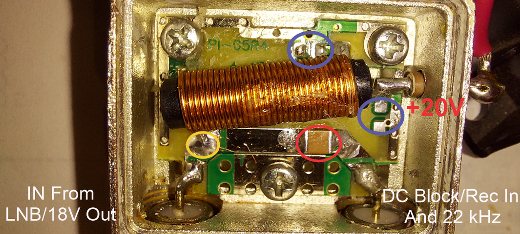
Out of curiosity I popped the cover off of the bias tee. I guess a picture would be better. Back in a moment.....
...flash. Back.

So initially the bias tee blocked 22 kHz out to the switch on the 18 V side. Lifted the inductor (yellow) and measured through the cap in red.
Still was blocked so increased the cap to a 100 nf.
That passed the tone through to the lnb port.
Soldered the inductor down. Lost the tone. So lifted the inductor at the other side. Got it back.
Removed one cap in blue, inductor soldered back. No tone.
Pulled the other cap. Now I got tone.
Soldered the psu back to the feed through and ground. Lost tone.

The other thing. The xml. In tuner setup you see your tuner. Same ole same ole. Except now you see H or V appended in the name.
And since I don't use usals, who cares what the orbital pos. is.
Thing is, it's done and ready to use. With all of the satellites pulled from the xml that will never be used.
131W - 40.5W. That's it.
Pasting in new found blindscan sats into it is easier also. That's my defense.
As for the dirty mod. If correct. Another run of coax or a juice wire would have to be sent to the dish. Correct?
Not exactly an option right now.

Bias Tee.png
 
  • Like
Reactions: Titanium
Late to the party, been out for awhile. I still run the old time Corotor turned by a servo motor. And separate C and Ku LNBs. No 5g out here, and I like my old setup.

What I do is use my analog box for dish moving and servo motor polarity. It’s also nice for fine tuning the rotation (especially dealing with snow). It has 18v ports for both a C and a Ku LNB.

I use the 13/18v from my FTA receiver for controlling C/Ku. Therefore all my C satellites are H, and all Ku satellites are V. When I blind scan, I do each satellite twice, each with the polarity turned manually by the analog box. Just channel up or down one to flip the polarity, no big deal.

The coax from the FTA box goes to an Eagle Aspen 13/18v multi switch. Got a few of them from a box of DIRECTV stuff in a roadside pile.

At the dish side of the switch, I put voltage block couplers. This lets the 13/18v run the switch, and the 18v run the LNBs, without interfering.

Then each coax goes to a basic splitter before going out to the dish. The 3rd leg of each splitter goes to the analog box, to send the 18v to each LNB.

Not sure how much of this is applicable to your setup, but hope it helps.
 
  • Like
Reactions: arlo
Late to the party, been out for awhile. I still run the old time Corotor turned by a servo motor. And separate C and Ku LNBs. No 5g out here, and I like my old setup.

What I do is use my analog box for dish moving and servo motor polarity. It’s also nice for fine tuning the rotation (especially dealing with snow). It has 18v ports for both a C and a Ku LNB.

Check. The ASC-1 will do the same. With a box of several corotor's it could be done here.
Read back. I have a good power cable with shielded sensor wires out the the actuator.
2 coax cables. One for the precious C2-W lnbf that has since totally went south and didn't stop at the border. Both ports now dead.
The other coax runs from the house to the dish also and is used for a sidecar ku lnbf.
That's it. Everything is in 2-1/2" pvc. And since being in the ground since the 80's. Nothing will budge.
A driveway has been constructed over the pvc. It's buried at least 3 feet to be below the frost line.
My yard has maybe 6" of topsoil and basically footbll and bigger boulders from there on.
There is actually a cable for the original corotor. It's defective and shows no continuity on any wire.
Stated.


I use the 13/18v from my FTA receiver for controlling C/Ku. Therefore all my C satellites are H, and all Ku satellites are V. When I blind scan, I do each satellite twice, each with the polarity turned manually by the analog box. Just channel up or down one to flip the polarity, no big deal.

The coax from the FTA box goes to an Eagle Aspen 13/18v multi switch. Got a few of them from a box of DIRECTV stuff in a roadside pile.

At the dish side of the switch, I put voltage block couplers. This lets the 13/18v run the switch, and the 18v run the LNBs, without interfering.
And that is my intention. Firstly using the directv 20V power supply/inserter to inject voltage to the pair of norsat lnb's with a tone switch.
The whole intention is to keep current load off of the receiver or ASC-1 lnb power circuitry.


Then each coax goes to a basic splitter before going out to the dish. The 3rd leg of each splitter goes to the analog box, to send the 18v to each LNB.
The splitters I have are all non power pass. And I continuously read. And know. That unless specially constructed. As is such for broadband/catv splitters that divide rf unequally.. Each port of a 2-way splitter attenuates the signal 3dB.
And also common sense and every single post here and elsewhere states never use a splitter in a fta setup.

Not sure how much of this is applicable to your setup, but hope it helps.
It could be all applicable. Power inserters are used commonly in the amateur radio world.
And I am quite familiar with using DC blocks to provide juice to a pole mounted preamp. They work.
Also for you average everyday TV antenna with a mast mounted preamp.


With just the dtv power inserter connected. Again. Firstly on my bench and injecting a 22kHz sine, square wave signal.
The tone passes the DC blocking capacitor and into port 1 (0 Volts) of the unpowered tone switch.
When I plug in the power inserter/suppply. All 22kHz disappears. Past the bias tee DC blocking capacitor. Out the lnb port. And then of course no tone at either switch ports. But there is 20 VDc at port 1.
It didn't 'hear' a tone. And hence did not switch.

Dirty. rotten, filthy mods aside...
Doing my homework a few things come to mind. With the diseqc packets and tone riding on 18 volts from the receiver/ASC-1. Is 20 volts out of the bias tee 'swamping' the multiplexed -in- port signal?

Secondly. Wondering if I bench just the bias tee and hook up a lab supply to it. If slowly ramping up the voltage with everything past the switch hooked up. Will I get tone with a variable voltage up to 18 VDC. And past that start losing it? Doesn't make sense really. It's a FTA-WTF situation.

Thirdly. A few. EB over legit included. Mentioned that both ports of the tone switch get juice and only the RF signal was passed when switched.
Reading also I need to use an Ecoda switch. I see Ecoda switches marked as such and then I see GeosatPro tone switches marked with Ecoda with their logo on them also. Is-there-a-difference? And if so, how?

I don't know if anyone has done business with Satellitedish. I gave them a call. Friendly and informative and not in a hurry. Was told that his commercial customers using DC block F couplers sliced the coax open past them to inject DC by connecting power to the stinger and shield and it worked. Very well.
Although until I can figure out how to get a tone out of a bias tee. Or where exactly a US vendor has Ecoda switches that don't cost an arm and a gizzard.
Still in the doldrums.

 
Coffee talk and such.

Even though I still haven't gotten the ortho mounted and setup just yet. The gears are spinning. Perhaps close though.

Google, search, more searching. Oh Holy Saint of Electrons and Beer!
How do I get two Norsat lnb's fed with around 20 VDC and a ku lnb to that switches with 13/18 volts over two coax lines with my OsMio4k?

As mentioned. I have an 8X1 diseqc switch that has worked flawless. My diagram above shows the concept method. Remove the DirecTV power inserter and ortho. Replace with my now defunct C2-W. And it just worked.

The DTV power inserter killed all 22 kHz going out to the dish. Google. Bias Tee low pass filter calculators. Try out different component values. Swap them out in the DTV bias tee. Inject a 22 kHz sine/square wave signal of different levels. With a 22 KHz switch on the input port (to lnb) and the Norsat's on the lnb ports of the tone switch. Feed the bias tee 20 VDC. So all impedance values are hopefully matched.
Nothing. No 22 kHz passes the bias tee isolation capacitor. And the filter design apparently not rejecting the tone. And diverting it to the lnb port.

The "hack" FTA sites and others mention using the Dishnet DP44 and DPP44 successfully. The ports on them are all named in DN jargon.
Take a chance? Covering one thing more below. Do they detect 22 kHz from the receiver and generate their own internally?
If that were the case. Probably would have had one already.
But the ports appear to still switch between 13/18 volts. I need a constant (at least) 18 volts.

The naughty mod isn't detailed enough for me to see exactly what's going on. Period. And melting and wicking up sealed can solder just-gets-old.

The ASC1. A big question is if it detects 22 kHz and generates its own out to the lnb(f) port.
And I see the specs listed. Seems adequate for current delivery. But still. I really don't wish to rely on the internal regulator circuit to power the Norsat lnb's and switches, etc.
So a bias Tee is the answer. Plus the added benefit that a capacitor isolates a 'zap' like killed my C2-W and still on the bench, in queue 'other' dead ASC1.
BTW. I now have massed 3 dead ASC1's for practically zilch. For another subject. Need to catch Brian on a good day. He's helped a lot. A whole lot.

So.....
Bias Tee. Power Injector, Voltage Controlled switch.Zinwell, Channel Master. eBay. Rack mount satellite head end bias tees.
Or Bias-T if you prefer.
Channel Master 5216IFD. Channel Master 8002IFD. Zinwell Voltage Controlled Multiswitch. Spaun.
Even a CM twin lnb power injector with an amp. Would that help with any insertion loss? Not into taking chances.
Down at the office, had to fill out the forms
A pink one, a red one, the colours you choose

And I actually had to slap on that record....they're only records. Enough with that vinyl crap. On the old Dual with a V15III. And a JICO SAS.
No documentation. No install and config guides to be found.
If it's just swapping a component on an LM317 to get 18 volts on a port. I'm cool with that.
And eBay? "Shipped from China". Nah.

My local second hand shop has a box of wall warts and power bricks and a few DTV power inserters.
I thought of gutting them and using the bias tees in parallel. I'm just way over Mickey Mousing things.

So I settled on a Tru-Spec SPI-18 power inserter. It has a switch to force the ports to 18 volts. Macom has the same thing with their own sticker. If it don't work....in 'the box' she'll go.

"If". And that's a very strong 'if' it works. I'll slap a weatherproof enclosure on my pole. Run the cables through proper cable glands.
Let's see. Two coax cables. Satellite on one, pixies on the other.

 
Top