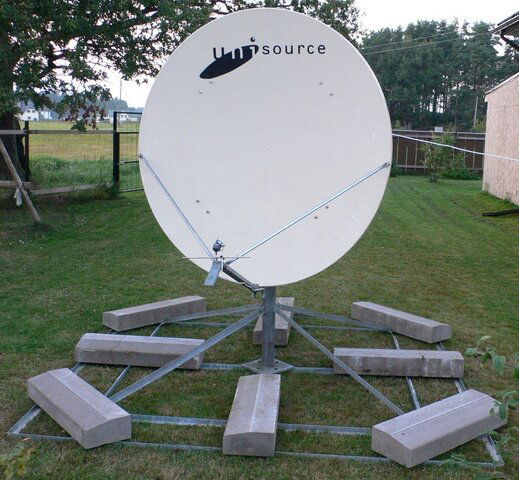
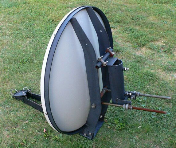
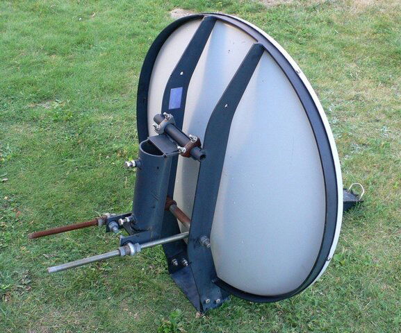
1.8 Mts Prodelin 0179-189
- Thread starter Tvsatelite
- Start date
- Latest activity Latest activity:
- Replies 55
- Views 29K
You are using an out of date browser. It may not display this or other websites correctly.
You should upgrade or use an alternative browser.
You should upgrade or use an alternative browser.
- Status
- Please reply by conversation.
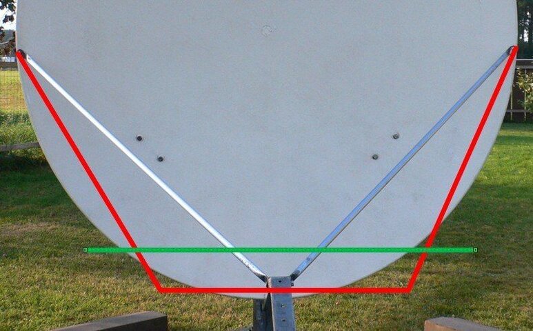
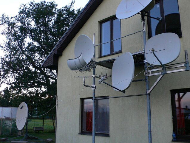
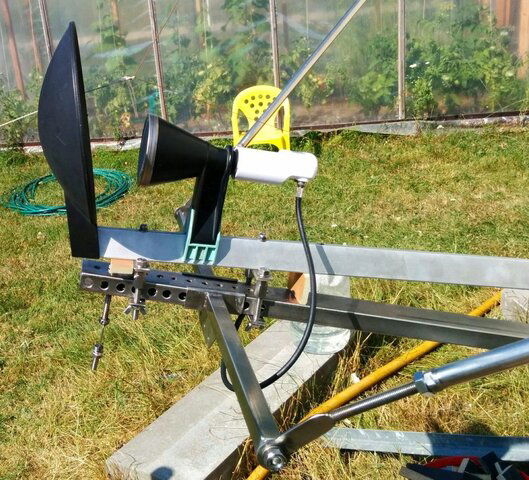
I will probably go this way on Proidelin multifeed issue: Will remove original support bars and make new ones out of INOX. To place them away from LNBs will make another piece horizontal bar and join everything together. Than, additional (green) bar will be connected and it will hold all LNBs.
Attachments
From my experience in setting up one of these the look angle is found like this. Maybe you already knew this but that one fact helped me greatly. These are great dishes.
http://www.satelliteguys.us/threads/248796-Given-two-dishes-today?p=2531106#post2531106
http://www.satelliteguys.us/threads/248796-Given-two-dishes-today?p=2531106#post2531106
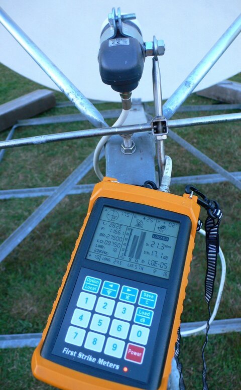
That was actually not so difficult to tune up and catch some signals...
- Leveled mount horizontally using original bubble-level;
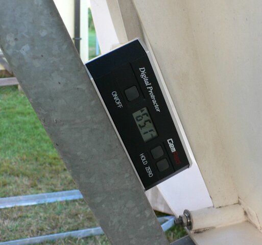
- Used digital protractor and set elevation to 24,9* for Astra 28,2*E (65,1* on protractor);
- Adjusted temporary holder of LNB;
- changed azimuth of antenna till I got lock;
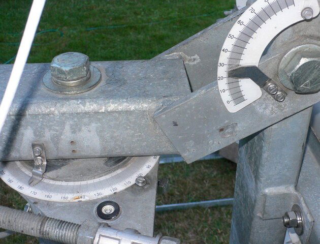
- adjusted original mount scales to ease future realignment of Prodelin;
- run temporary cable (about 30 meters, consisting of 3 pieces connected together) from antenna to receiver;
- with all that got approximately same level of signal as I am getting from 1,5m PFA.
Unfortunately I did not have lots of time to this. Another day will need to do more precision tweaking and change all temporary stuff for permanent one.
And, yes, drunk couple of tequila shots during this..... operation

Attachments
Thanks chapelrun!
I have digital protractor, for sure I am going to use it for finding some bird. How your Prodelin is doing? Is that pained on your avatar?
I repointed a while ago to 125W for some C-Band channels in the clear. I had been pointed at 133W for one of the few analog channels but it converted to newer technology.
As for the painting - - - the whole story is told here. http://www.satelliteguys.us/threads/262542-Beautiful-Dish-Painting!!!
BTW, I really like you dish setup - - - your dish has way more cool adjustments than mine!
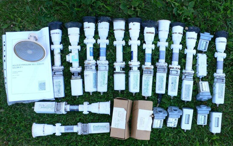
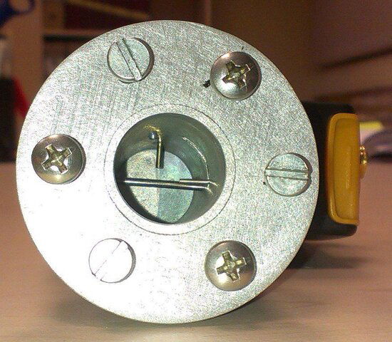
I've got box of spares today. Is that feedhorn (left upper corner) original Prodelin? Will try to install it, just need some flange LNB.
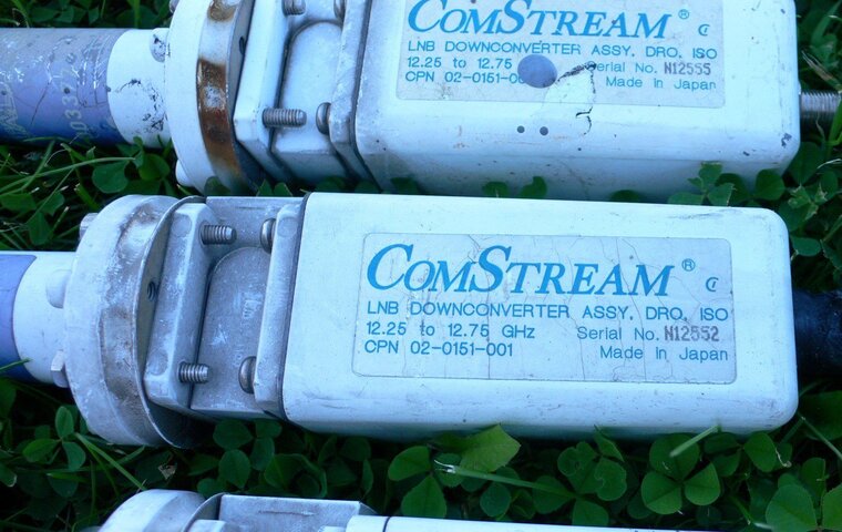
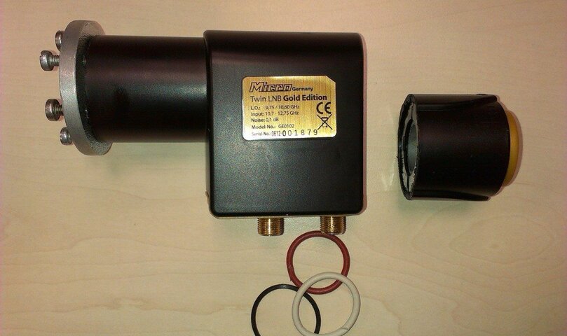
And those old, made in Japan LNBs.... can they still be used today? Some still in original, unopened boxes.
And those old, made in Japan LNBs.... can they still be used today? Some still in original, unopened boxes.
Attachments
The one really large feedhorn might be original.I've got box of spares today. Is that feedhorn (left upper corner) original Prodelin? Will try to install it, just need some flange LNB. And those old, made in Japan LNBs.... can they still be used today? Some still in original, unopened boxes.
All the small ones are not (but would probably work).
.
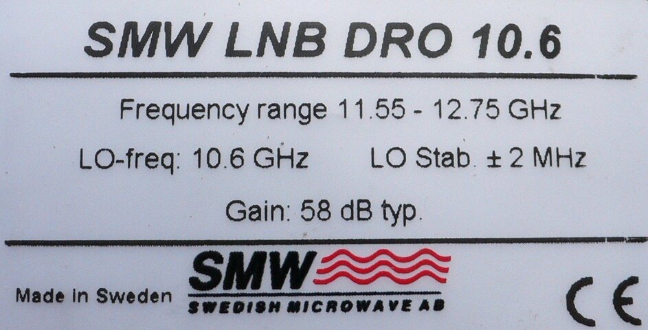
The frequency range printed in the LNBs seems wrong.
At least for use in North America.
Is there any marking showing the LO (local oscillator) frequency?
?.
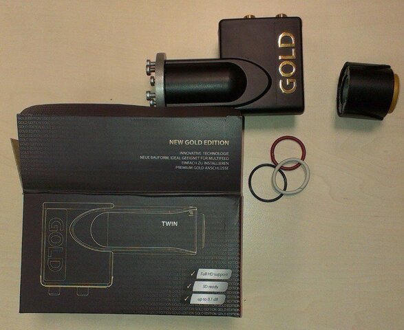
I was mislead by carbon box, seems that it belongs to another LNB. Those down-converters I've got are exactly same I've found on e-bay _http://www.ebay.com/itm/LNB-COMSTREAM-Ku-Band-12-25-to-12-75-GHZ-Downconverter-/111137962374?pt=LH_DefaultDomain_0&hash=item19e056%20b986
and they have L.O. frequency 11,3 GHz. So, I've managed to get signal, which was actually not better than universal SHARP LNB provides. Basically, I do not see how can I use those old LNBs, and mostly because of very limited frequency range.
One practical question:
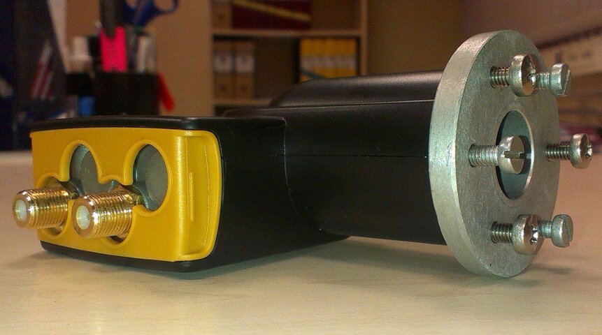
If I decide to use Ivacom flanged LNB (which I do not have yet) and attach it to original Prodelin feedhorn, what is better way to do that? LNB has 8 holes and feedhorn has only 6. Should I use some kind of adapter between them? And, of course, I will be disappointed if after installing original feedhorn and expensive Ivacom LNB will be worse than with simple (5 bucks ) universal LNB. Any advice is appreciated.
Attachments
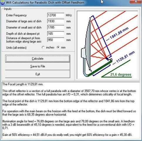
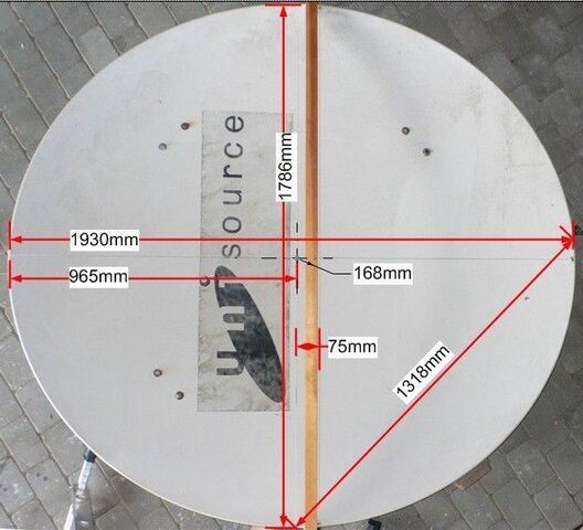
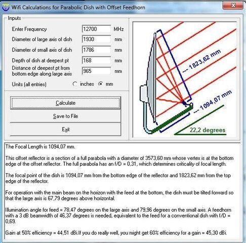
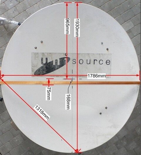
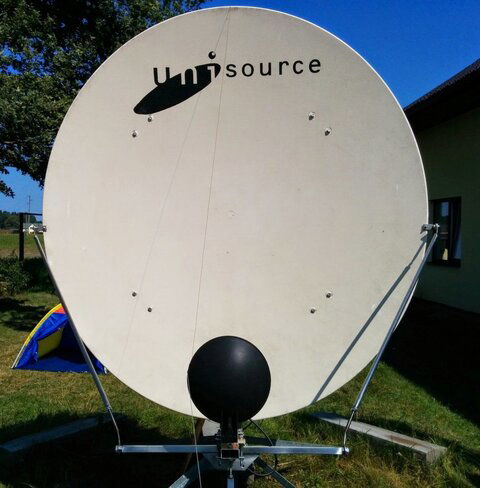
made precise measurements of Prodelin today, than entered all data in Parabola Calculator 2.0. Programme gave following. I think it is close to be true.
Attachments
Last edited:
Have the feeling the LNB support arm would be on the dish on the right side of the picture. So - I think I spotted an error in post #33
The picture is sideways. The "height' is positioned where width should be.
Measuring the deepest part of the dish is being performed across the width of the dish. (straight edge across the width. Think the straight edge should be positioned across the 1930MM 'height'.
Then measure from the bottom, (right side in picture) LNB arm side of the dish, to the point deepest from the straight edge.
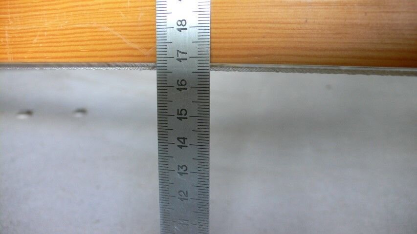
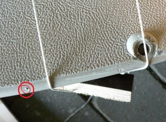
That could be matter of visualization. The deepest point of antenna is measured from point where is cross of vertical axe and horizontal line from special marks on antenna (circled red). This horizontal line is about 75mm from line which connects arm's connecting holes.
Attachments
Could be, but to my knowledge, if the deepest point is the physical center of the dish, it wouldn't be an offset, it would be a prime focus. Along the 1930 measurement string. it's actually the greatest measurement from that string, to the dish face, is exactly one half of 1930 (965)?
The 75mm measurement is immaterial. This is not part of the measurements required
The calculator asks for - Depth of dish at deepest point. (along and from the long axis string)
Measurement of the distance, of the deepest point, along the large axis from the bottom of the dish (edge where the lower lnb support arm attaches or goes around).
Just don't want you getting mediocre performance, Measure twice/cut once.
The 75mm measurement is immaterial. This is not part of the measurements required
The deepest point of antenna is measured from point where is cross of vertical axe and horizontal line from special marks on antenna (circled red).
The calculator asks for - Depth of dish at deepest point. (along and from the long axis string)
Measurement of the distance, of the deepest point, along the large axis from the bottom of the dish (edge where the lower lnb support arm attaches or goes around).
Just don't want you getting mediocre performance, Measure twice/cut once.
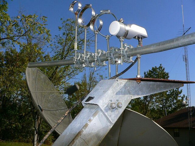
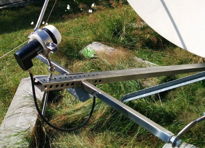
Made adjustable feedarms for my Prod, also possible now to make multifeeds.
View attachment 99453
Wait a minute. You MADE this?? Like, from scratch? It looks like something factory made!
Please tell me this is something you bought somewhere and not a one of a kind "only one in the universe" kind of thing !!
- Status
- Please reply by conversation.
Similar threads
- Replies
- 4
- Views
- 354
- Replies
- 3
- Views
- 1K
- Replies
- 2
- Views
- 2K
- Replies
- 2
- Views
- 2K


