I can't believe it has been nearly two months but after being distracted by several problems lately I finally got back to adding a fan to this receiver to address the overheat issues it was having. I had planned on mounting a 60mm fan to the top of the case but decided to really make a project of it and see if I could fit one inside instead. The voltages available from the power supply are 5VDC, 15VDC and 20VDC. I was going to use a voltage regulator on the 15VDC output to feed a 12VDC fan but with very little room inside and the regulator possibly adding some additional heat I decided against it. I went with a 5VDC fan instead since that was readily available. The power supply is always on when the receiver is plugged in which means the fan would always be on as well. I briefly considered looking for a signal on the main board to use to control an add-on circuit to turn the fan on and off along with the receiver but with the lack of space and use of surface mount technology I just opted to add a simple toggle switch to control the fan. I ordered a 60mm x 60mm x 10mm fan from ebay and used a small toggle switch that I had in my parts bin. When the fan arrived the screws that came with it were the wrong size  but luckily I had some in my parts bin.
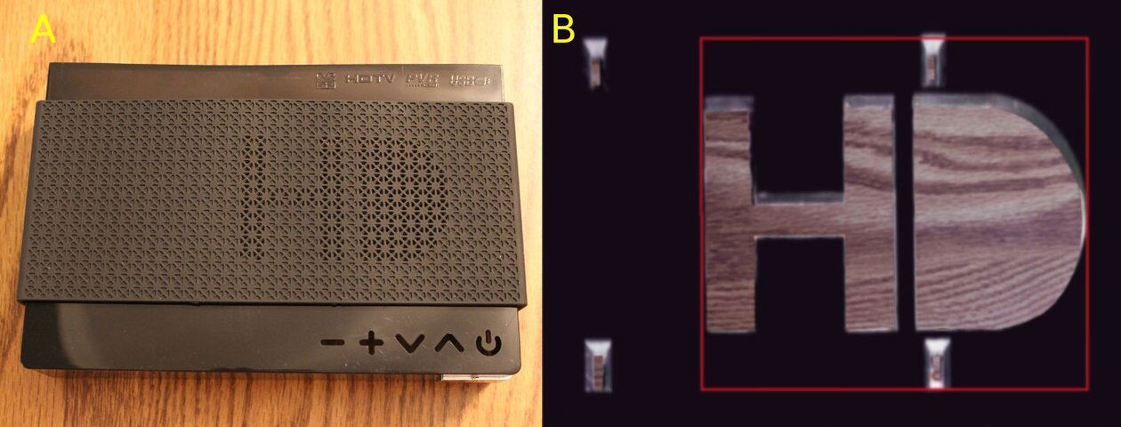
The cover for this receiver is actually two separate pieces with one part snapping over the other (A). Even with only a 10mm thick fan the inner part of the cover and the connector for the display/control board needed some modification otherwise the blades would hit the capacitors and that connector on the main board. The red lines show the section of the case that I removed (B).
First I cut out the plastic sections that create the HD logo then I used a small C clamp and straight metal piece as a cutting guide to cut the left and right areas with a fine hacksaw blade (A). I carefully scored the top and bottom lines (B & C) several times with a utility knife and then snapped the pieces out. After cleaning up the edges a bit with a small file you can see the finished fan hole (D).

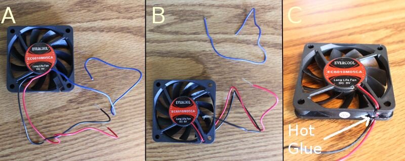
The fan I ordered had three wires so I had to remove the blue tach wire (A & B). I used some hot glue to fasten the two power wires to the fan body (C).
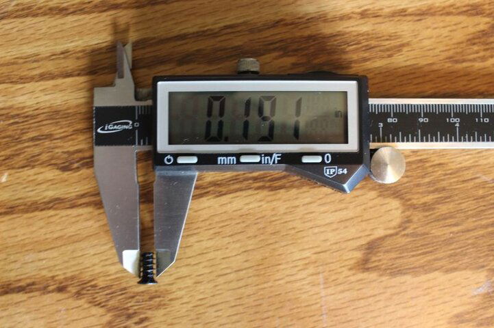
To get the outer piece of the case cover ready for securing the fan to it I needed to drill four holes. They had to be large enough that the screw threads could slip easily through the cover but not too large that the heads went through. The screws I used had an outer thread diameter of .191" and a head of .24" so a 13/64 (.203)" bit worked for me.
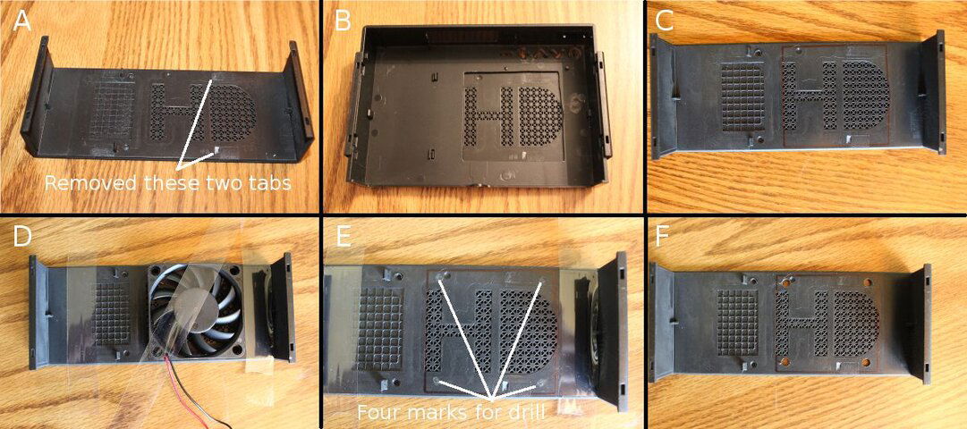
I removed two of the four tabs that help hold the center of the mesh cover in place (A) and put the two cover pieces back together to mark where the fan will go (B). After pulling the pieces apart again the fan location can be seen (C). I taped the fan in place (D) and made marks where the mounting holes needed to be drilled. After untaping the fan you can see the drill marks in pic (E) and the finished holes in (F).
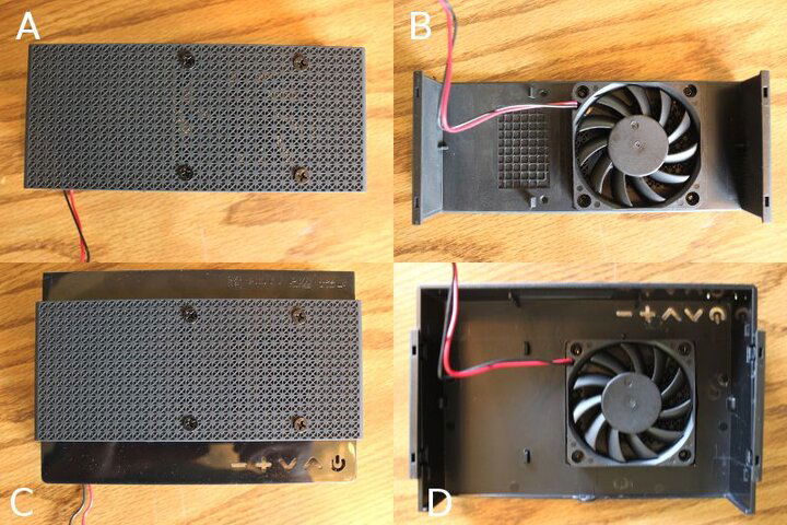
I attached the fan to the outer piece (A & B) and snapped the two cover pieces back together (C & D). I forgot to take a pic of this but I also drilled a 1/4" hole in the front left corner to mount the toggle switch.
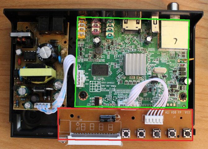
Now for the electrical work. I unplugged the connectors and removed the display/control board (red section, snaps in/out) and main board (green section,unscrews) from the lower part of the case.
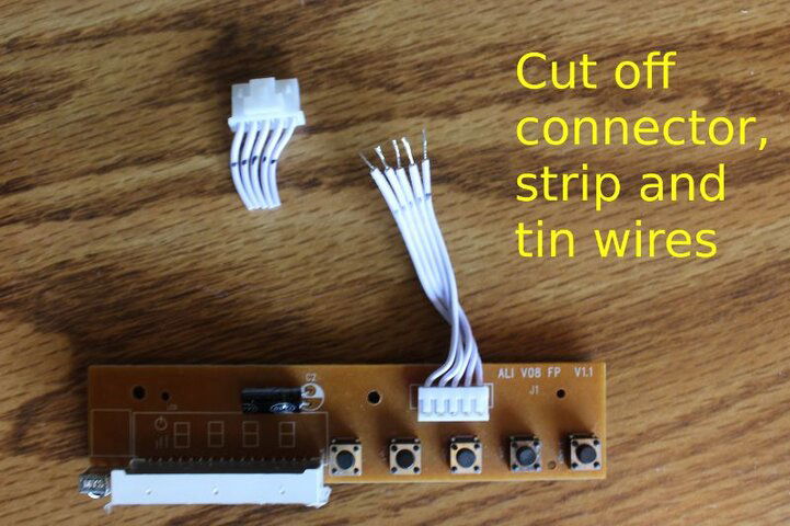
I cut the plug from the display/control board assembly, stripped & tinned the five wires.
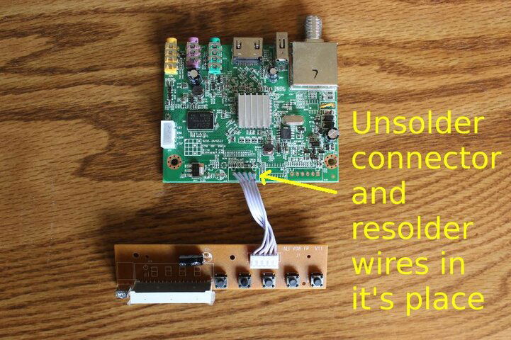
Unsoldered the display/control board socket from the main board and soldered the tinned wires in it's place making sure solder flowed to the pads on both sides of the board.
To get power for the fan I cut the +5VDC and GND wires to tap into them
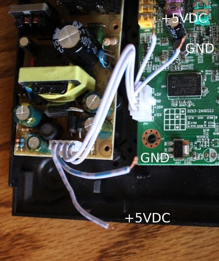
and added the toggle switch wire (from positive side fan) to the +5VDC wires and the negative fan wire to the GND wires, soldered all connections and put heat shrink tubing over them.
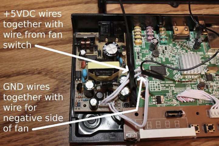
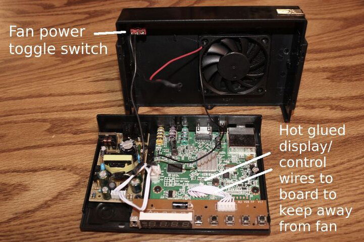
Here is the inside finshed. I also added some hot glue to the display/control wires to fasten them to the main board for better fan clearance.
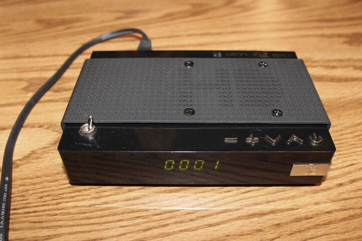
After tucking the wires in neatly and putting the cover back on here is the finished receiver.
The cover for this receiver is actually two separate pieces with one part snapping over the other (A). Even with only a 10mm thick fan the inner part of the cover and the connector for the display/control board needed some modification otherwise the blades would hit the capacitors and that connector on the main board. The red lines show the section of the case that I removed (B).

First I cut out the plastic sections that create the HD logo then I used a small C clamp and straight metal piece as a cutting guide to cut the left and right areas with a fine hacksaw blade (A). I carefully scored the top and bottom lines (B & C) several times with a utility knife and then snapped the pieces out. After cleaning up the edges a bit with a small file you can see the finished fan hole (D).

The fan I ordered had three wires so I had to remove the blue tach wire (A & B). I used some hot glue to fasten the two power wires to the fan body (C).

To get the outer piece of the case cover ready for securing the fan to it I needed to drill four holes. They had to be large enough that the screw threads could slip easily through the cover but not too large that the heads went through. The screws I used had an outer thread diameter of .191" and a head of .24" so a 13/64 (.203)" bit worked for me.

I removed two of the four tabs that help hold the center of the mesh cover in place (A) and put the two cover pieces back together to mark where the fan will go (B). After pulling the pieces apart again the fan location can be seen (C). I taped the fan in place (D) and made marks where the mounting holes needed to be drilled. After untaping the fan you can see the drill marks in pic (E) and the finished holes in (F).

I attached the fan to the outer piece (A & B) and snapped the two cover pieces back together (C & D). I forgot to take a pic of this but I also drilled a 1/4" hole in the front left corner to mount the toggle switch.

Now for the electrical work. I unplugged the connectors and removed the display/control board (red section, snaps in/out) and main board (green section,unscrews) from the lower part of the case.

I cut the plug from the display/control board assembly, stripped & tinned the five wires.

Unsoldered the display/control board socket from the main board and soldered the tinned wires in it's place making sure solder flowed to the pads on both sides of the board.

To get power for the fan I cut the +5VDC and GND wires to tap into them

and added the toggle switch wire (from positive side fan) to the +5VDC wires and the negative fan wire to the GND wires, soldered all connections and put heat shrink tubing over them.

Here is the inside finshed. I also added some hot glue to the display/control wires to fasten them to the main board for better fan clearance.

After tucking the wires in neatly and putting the cover back on here is the finished receiver.


