Rabbit73
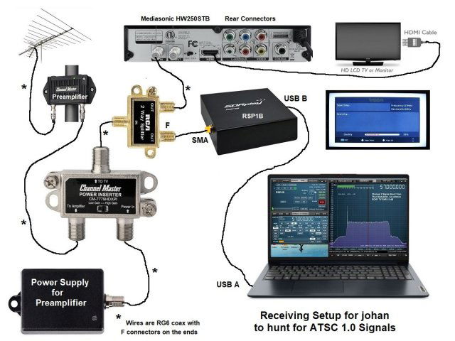
Do you have a photo or drawing of what is between your antennas and the receiver, in terms of splitter or amplifier. because I am overwhelmed with information. Everything well intentioned.
Mvg
I apologize if my previous post was confusing and overwhelmed you with too much information.
My setup was more complicated than what your setup will be for reception. My setup had to add a modulator to create a Channel 2 signal because I don't have any VHF-Low 2-6 channels here. I had to add an attenuator to the channel 2 modulator signal to show you different signal waveforms with the RSP1B for different SNRs to help you find an ATSC 1.0 signal:
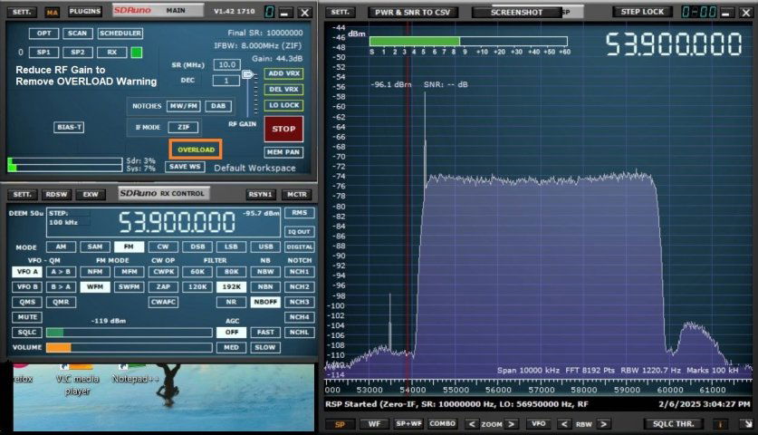
1. Very Strong signal, SNR 31 dB, good picture on TV
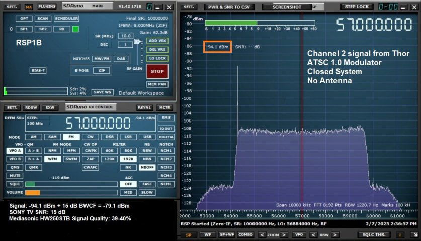
2. Good signal, SNR 15dB, just enough for picture
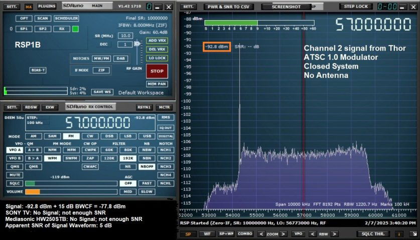
3. Weak signal, SNR 5 dB, NO picture on TV
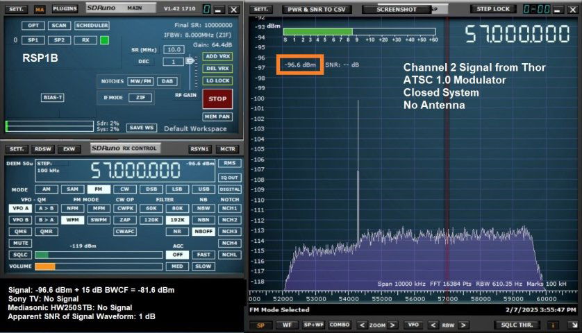
4. Very Weak signal, SNR 1 dB, NO picture on TV
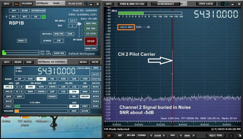
5. Extremely Weak signal, SNR about -5dB because the signal is buried in the noise with only the Pilot Carrier showing above the noise at 310 kHz above the low end of the channel. In the case of CH2 the pilot is at 54.310 MHz
Yes, there is such a thing as a negative SNR.
I will draw a diagram of the setup you will need with your RSP1B, but it will take some time to do it. I will post it when I have completed it.