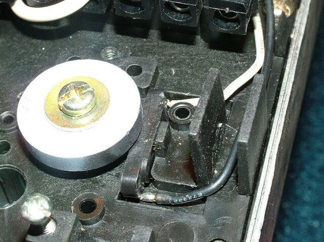
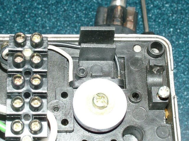
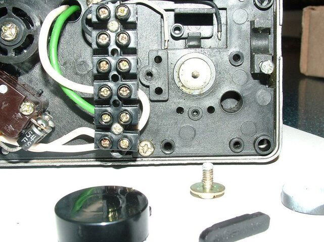
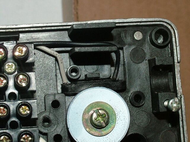
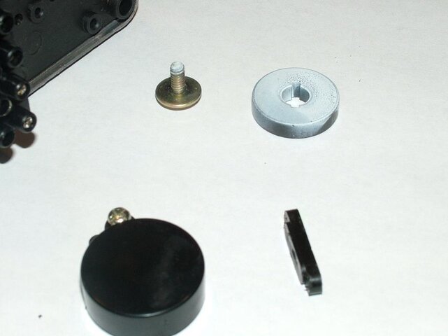
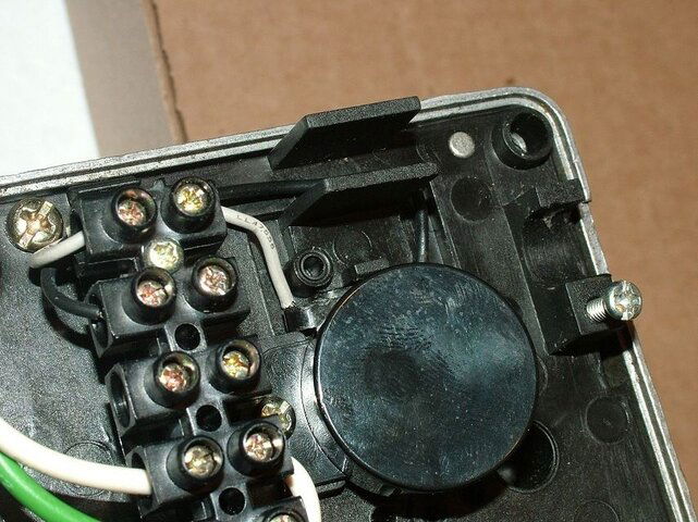
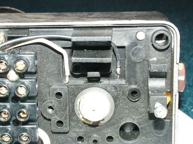
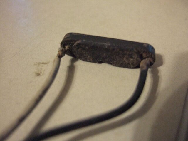
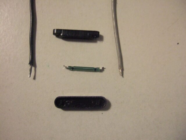
OK, it looks like the two wires go *under* the little plastic thingy, which is partly under the magnetic wheel? So, that means it doesn't weld anywhere, it's just held, somehow, by the plastic piece? And it does its job by *sensing* the magnatic movement of the wheel, by proximity (and therefore no contact)?
Positioner wiring
- Thread starter pjcl
- Start date
- Latest activity Latest activity:
- Replies 51
- Views 13K
You are using an out of date browser. It may not display this or other websites correctly.
You should upgrade or use an alternative browser.
You should upgrade or use an alternative browser.
- Status
- Please reply by conversation.
Thanks for the email.I wonder if this how it should go...
Unfortunately, I've never dealt with a motor like this one.
Your nice wiring diagram show the internal (non-connected) black and gray wires should go to the reed switch
It is a little glass capsule, with a wire on each end.
From all the pictures, it looks like the capsule is molded into a more rugged plastic housing.
None of the pictures are clear, but I think the plastic block should have a wire or terminal on each end to connect the black and gray wire to.
If you could remove the black molded reed switch module and show us a picture of the bottom, that would help.
Alternately, look underneath, and solder your black/gray wires to it, if possible.
Anole, unfortunately that plastic piece does not have a terminal, or any signs of where said wires connect to. I'm guessing the wires are supposed to go under the plastic thingy and be held in place by it. Now, conceptually speaking, is this how a reed sensor works - two sensor wires *near* a magnetic wheel, wires which sense the change in polarity of said wheel as the dented wheel rotates underneath?
The wheel has about 8 poles of a magnet inside it.
It rotates over a reed switch (two flat metallic reeds which snap together when subject to a magnetic field).
Without seeing the bottom of the black molded item in question, I can't offer any further info on how the wires connect to it.
Perhaps someone who's disassembled one of these motors can offer a better hint.
The pictures just don't convey enough info to make an educated guess.
More pics
Anole, here's a few more pics. You can see the the little parts and how they *seem* to go. The little plastic bar does not have any terminals on it. The last picture shows the assembly with another plastic cover on the magnetic wheel. Now, if I were to test this as is (by connecting all the wires out of the V-box), would the wheels just spin if I keep east or west button depressed? Because before (without the black/gray wires connected), it just moves one click at a time. As you said elsewhere, it basically says "I can't sense the movement, so I'm stopping for safety reasons"...
Anole, here's a few more pics. You can see the the little parts and how they *seem* to go. The little plastic bar does not have any terminals on it. The last picture shows the assembly with another plastic cover on the magnetic wheel. Now, if I were to test this as is (by connecting all the wires out of the V-box), would the wheels just spin if I keep east or west button depressed? Because before (without the black/gray wires connected), it just moves one click at a time. As you said elsewhere, it basically says "I can't sense the movement, so I'm stopping for safety reasons"...
Attachments
let me find my reed sensor and take a pic . --> you must remove the reed sensor from the plastic case and reconnect the wire ends and then put all back together .
Looks like time to a new Reed Sensor.
Do you really think so, Lak?
If you can not solder the wires back on, what choice do you have?
Unless you have a Spare Arm laying around.
Unless you have a Spare Arm laying around.
Last edited:
yep!
Any idea about the specifications - supply voltage, supply current, operating supply voltage, and sensing distance? MouserElectronics has a bunch of these, and all different...
The important thing to make sure of is that your magnet wheel will activate the reed switch without damaging it. If the reed switch is for a stronger magnet, it wont work, if it is for a weaker magnet the reed switch may get damaged over time. This is a low voltage sensing circuit, probably 5v to 36v, depending on the receiver/positioner. The switch is carrying very low current, most likely less than 200mA. If someone with the same actuator can supply the manufacturer and model number of the switch, you would be best off.
Bongu, thanks for your input. It has been difficult to find this exact actuator. I was just looking at this product:
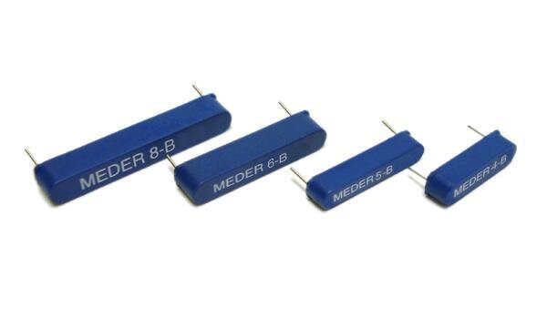
MK06-8-H MEDER electronic Proximity Sensors
Do you think it will work?
MK06-8-H MEDER electronic Proximity Sensors
Do you think it will work?
- Status
- Please reply by conversation.
Similar threads
- Replies
- 3
- Views
- 905
- Replies
- 13
- Views
- 2K
- Replies
- 20
- Views
- 4K
- Replies
- 4
- Views
- 2K
- Replies
- 3
- Views
- 1K


