I hope for this to be a continuous work in progress, and we can learn and accomplish something along the way. The more that play the more we will all learn.
I ordered that servo controller kit I mentioned in the G box thread. For anyone interested, I ended up getting it from here -
The sales rep's name was Sue. Very courteous and professional. I told her a bunch of yall would be calling too!
I also picked up some 556s and sockets to build the PWM test rig.
I did not find what I was looking for in the remote control dept...........yet. I imagine something is commercially available, but cost eventually becomes an issue.
I had a couple of thoughts. One will require the assistance of our appointed PIC subject matter expert. If the PIC16C71-04/P has the room for the code to learn, and act on existing IR commands at our disposal, all that would be needed is to add a 38khz ir detector and supporting code. What do you think Cad? I'll post the code for the PWM unit at the end of this post.
The other idea I had involved some HW mods to our various STBs. I've been eyeballing the useless tv/vcr function on my remotes and wondering if I could intercept that control sig and route it to a jack on the back of the rx and use it as an input state [H or V] to the PIC. Things that make you go hmmmm........
Here's the code per the .pdf Cadsulfide. Please comment. It's all geek....er, uh, greek to me........lol
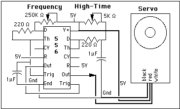
Here is the pic of the 556 based servo test rig, courtesy of Tom Dickens -
I ordered that servo controller kit I mentioned in the G box thread. For anyone interested, I ended up getting it from here -
Code:
h[COLOR="Red"]XX[/COLOR]p://www.electronics123.com/s.nl/it.A/id.316/.fI also picked up some 556s and sockets to build the PWM test rig.
I did not find what I was looking for in the remote control dept...........yet. I imagine something is commercially available, but cost eventually becomes an issue.
I had a couple of thoughts. One will require the assistance of our appointed PIC subject matter expert. If the PIC16C71-04/P has the room for the code to learn, and act on existing IR commands at our disposal, all that would be needed is to add a 38khz ir detector and supporting code. What do you think Cad? I'll post the code for the PWM unit at the end of this post.
The other idea I had involved some HW mods to our various STBs. I've been eyeballing the useless tv/vcr function on my remotes and wondering if I could intercept that control sig and route it to a jack on the back of the rx
Here's the code per the .pdf Cadsulfide. Please comment. It's all geek....er, uh, greek to me........lol
Code:
;KIT 102. SERVO-MOTOR DRIVER
dummy = 14h
flag = 15h
servo0 = rb.5
servo1 = rb.4
servo2 = rb.3
servo3 = rb.2
org 0
jmp start
org 4 ;Interrupt jumps here
clrb RTIF
setb flag.0
reti
start mov !ra, #255 ;Set ra to input.
mov !rb, #0 ;Set rb to output.
clr rb ;Clear port rb
mov dummy,#255
mov intcon, #0 ;Turn interrupts off.
mov adcon0,#AD_ctl ;Set AD clock and channel.
setb rp0 ;Enable register page 1.
mov adcon1,#AD_ref ;Set usable pins, Vref.
mov option,#00001000b ;WDT on, no prescale
clrb rp0 ;Back to register page 0.
setb adon ;Apply power to ADC.
setb go_done ;Start conversion.
not_done snb go_done ;Poll for 0 (done).
jmp not_done ;If 1, poll again.
mov counter2,adres ;Move ADC result into counter.
mov integer1,#3 ;Offset constant
mov integer2,#5 ;ADC multiplier
setb servo0 ;Output pulse to servo 0
call delay
clrb servo0
call pause ;ADC settling delay
clrb rp0 ;Ensure reg page 0
clrb chs1 ;Select channel 1
setb chs0 ; Ain 1
mov dummy,#255 ;Reload dummy variable
clrb adres ;Make sure
setb go_done ;Start conversion.
not_done1 snb go_done ;Poll for 0 (done).
jmp not_done1 ;If 1, poll again.
mov counter2,adres ;Move ADC result intocounter.
mov integer1,#3 ;Offset constant
mov integer2,#5 ;ADC multiplier
setb servo1 ;Output pulse to servo 1
call delay
clrb servo1
call pause
clrb rp0 ;Ensure reg page 0
setb chs1 ;Select channel 2
clrb chs0 ; Ain 2
mov dummy,#255
clr adres
setb go_done ;Start conversion.
not_done2 snb go_done ;Poll for 0 (done).
jmp not_done2 ;If 1, poll again.
mov counter2,adres ;Move ADC result into counter.
mov integer1,#3 ;Offset constant
mov integer2,#5 ;ADC multiplier
setb servo2 ;Output pulse to servo 2
call delay
clrb servo2
call pause
clrb rp0 ;Ensure reg page 0
setb chs1 ;Select channel 3
setb chs0 ; Ain 3
mov dummy,#255
clr adres
setb go_done ;Start conversion.
not_done3 snb go_done ;Poll for 0 (done).
jmp not_done3 ;If 1, poll again.
mov counter2,adres ;Move ADC result into counter.
mov integer1,#3 ;Offset constant
mov integer2,#5 ;ADC multiplier
setb servo3 ;Output pulse to servo 3
call delay
clrb servo3
sleep
jmp start ;Time out after 18 msec
; The number of loops this delay routine makes is dependent on the result of
; the AD conversion. The higher the voltage, the longer the delay.
delay clrb rp0 ;Page 0
mov intcon,#10100000b ;Enable RTCC interrupt
;****************** Fixed delay part of routine ****************
delay1 mov RTCC,#55 ;Fixed delay
wait1 jnb flag.0,wait1 ; of 200 till interrupt
clrb flag.0 ;Flag set on interrupt
djnz integer1,delay1 ;Three times through
;****************** Variable delay part of routine **************
sub dummy,counter2 ;RTCC counts UP!
load mov RTCC,dummy ;Load RTCC
wait2 jnb flag.0,wait2 ;Note infinite loop
clrb flag.0
djnz integer2,load ;Five times through
mov intcon,#0 ;Disable interrupt
ret
pause mov counter1,#120 ;Adds a short settling
settle djnz counter1,settle ; time to the ADC
ret
*************************************************************Attachments
Last edited:


