Pendragon vs. the Birdview

Status
Please reply by conversation.
Anole - I didn't do anything about the overshoot, but with the dish on the motor it tends to be less.
Perhaps the motor is running slower or there's more friction compared to my original tests with the motor assembly resting on a bench.
Yea, more damping, that sounds likely. - :up

I was going to forward an idea I've been holding in reserve, should it still be a problem.
That is to pulse modulate the power to the DC motor.
Makes 'em run slower, but maintains torque.
Not a good overall solution, but maybe if you could engage the slow-mode when approaching the end of travel... but that's a whole 'nother project! ;)
(I did this on model trains a decade ago, and was shocked at how slow you could creep!)

In terms of Ku reception, I'm happy with it as it's the best I've seen on a BUD.
In fact the Birdview is now the #2 Ku dish in my stable. ...
I may take the lazy route because my 1.8m Prodelin has always sufficed for tough Ku feeds.
You did wonders with the 6' Prodelin, so I look forward to what you can pull out of your hat on the Birdview.
I wouldn't be surprised to see equal performance.
Doubtful without a dedicated Ku ortho or your Invacom scalar & LNB, though.
Birdview did a hell of a job, back in the day! - :up

Oh, and speaking of the Prodelin on the AJAK H-H mount, that's a nice positioner, too.
Clever how they got 10 pulses out of 5 magnets, eh?
I was lmao when I realized what they did!
But, now that you've got that cheap rotary encoder under control, do you see a future for one on the AJAK?
 
  • Like
Reactions: Hockeynut
Conceptually the rotary encoder could work the same on an Ajak mount because both it and the Birdview drive a half-moon gear from a worm. One would only need to figure out a way to couple the encoder to the worm gear shaft. I've been thinking about this, but my evil mind keeps drifting down another path...

The same company that makes this encoder sells a variation as an absolute rotary encoder. As a future project I've been toying with mounting this to the polar shaft and measuring the shaft position directly. That would obviate any issues of backlash and prevent the loss of counts, which tends to be caused by user error here. One of the rubs though is the resolution is 4096 counts for 360 degrees, or 0.088 degrees per count. That might be enough for C-band, but a stock Ajak already gets about 0.05 degrees per count. From my Birdview work, I would not want to suffer on Ku.

I haven't looked to see if there might be a reasonably priced encoder that provided more accuracy, but I had also been considering something very close to what you had also mentioned - PWM the drive. The concept would be to lower the motor speed as it got close, measure the time between the 'clicks' and interpolate for a more accurate stop. My plan was to build a custom GBOX-like unit, but preferably with a USB interface. I would like one of my Linux servers to run all of my positioners, be able to interrogate them for interpolated positions and dynamically make small tracking adjustments to maximize the CNR for a given signal being captured on a PC tuner.

As for improving Ku, that may be more fun than useful. For the moment the Birdview replaces my former 1.8m Fortec and will stay on 58W most of the time for home theater purposes. I have an occasional need for two high-gain Ku dishes, and the Birdview is already good enough to play second fiddle to the Prodelin. That's a big relief because the Fortec was impossible to keep dead-on the Ku arc, and my 1.2m offsets don't quite have enough gain for some of these feeds while also being susceptible to high wind.

Of course I dream of getting the Birdview to beat the Prodelin on Ku. I really am bothered by how poorly dual ortho feeds perform on Ku. Given that the Ku side by definition lacks a proper scalar, it's probably not surprising the beam pattern and the fields are poorly matched. But I'm struggling for this to add up to 3+ dB. If this is caused by the dish surface then I'm fine. Otherwise I'll be looking for an approach to keep good C-band performance but boost the Ku side. While a siamese feed wouldn't be as elegant as a better tweaked dual ortho, theoretically one could keep the Ku losses very low and improve the C-band side by half a dB or so by using a single ortho. So the mystery continues.
 
  • Like
Reactions: Hockeynut
This weekend was focused on the rather dull aspects of reattaching siding and custom fitting an exact hole to seal the attic. I have been making a few minor alignment tweaks, and over the past week an unscientific comparison survey now suggests the Birdview is on par with my 1.8m Prodelin performance. It may even be better as the crummier of my two Invacom LNBs ended up on the Birdview. I'm planning the Ku-only feed shootout, but nothing concrete on that yet.

To answer an earlier question, I made several measurements of my fixed Birdview declination angle on the pole and concluded it's about 5.7 degrees. That's just a little higher than I would like, but about where my gut was feeling. For the time being I'm 'living' with the Birdview to get a clear idea of where to go next.
 
  • Like
Reactions: Hockeynut
A year has passed and today I received a inquiry from Anole about how the Birdview story ended. The only FTA stories I've ever finished are when I've decommissioned something and given it away to someone I'll never see again. As for the Birdview, it's served very nicely with little attention since I last wrote about it.

As some of you might have read on Rick's, I was able to nail Brazilian Ku DBS beams here in Denver on the Birdview, which barely registered on my bench spectrum analyzer with the 1.8m Prodelin offset. So it seems there are at least parts of the Ku band where the Birdview offers 1-2 dB more gain. However the Birdview doesn't always win. My gut is the beam pattern is not as clean on the Birdview, because of its dual ortho feed, and varies more across the band. I also know the Ku LNB on the Birdview turns in slightly lower CNRs on average than the one I have on the Prodelin (they are the same model). Also at Rick's, Captain and I had some consistent comparisons of similarly configured Birdviews, and which LNBs tested the best. I won't repeat that here.

I haven't changed the scalar since that time, as that setup is good enough for any need I've had. For awhile I considered the Birdview my #1 Ku dish, but then I ran into a nasty wind storm where the Birdview wasn't able to hold lock on a tough Ku feed. The mount was absolutely rock solid, but the dish itself was flexing in the wind. I moved the Prodelin over and it held lock for hours.

But at least the Birdview is still here. A few weeks ago we had the highest winds I've ever experienced, at or above near hurricane range. One of my toroids twisted on its pole, which has never happened before, and one of my 1.2m GeoSatPro solid offsets snapped its C-band HH motor in half. I checked all of my dishes afterwards, and the Birdview still tracks the arc on Ku as well as it did a year ago. I've never touched the alignment after the initial setup. The rotary encoder mod has held up well. It provides laser accuracy on Ku, which I can't quite achieve on the Prodelin. Although it would be fun to expand rotary encoders to my other dishes with motors, they work well enough and I can never find enough time to work on higher priorities.

Most of the time the Birdview is wasted capturing 58W C-band for our whole house satellite system. It's a real pleasure not having to navigate across a treacherous, icy roof every few weeks to realign the 1.8m prime-focus Fortec it replaced. When I need a second high gain Ku dish, it's wonderful to have it in the stable. The Birdview's C-band performance is good, but nothing special for its size. My 3.0m Winegard perf stomps it by at least the theoretical margin, and my 2.3m Winegard mesh is within spitting range of the Birdview's C-band gain (the Birdview is about 2.6m). Admittedly I'm giving up 0.5 dB in gain on the Birdview with its dual ortho feed, while the Winegards have single orthos (all the same LNB). However rough measurements indicate a bit more loss for the Bordview overall.

For the time being I've tabled my Birdview projects. I've been way too busy with work and family to have much free time. Most of what I've been doing in FTA is software, but have still a lot to write. I do have dreams for major FTA projects down the road, but they will have to wait. All-in-all the Birdview was a highly successful project and a great addition to the farm.
 
  • Like
Reactions: Hockeynut
I noticed a few questions, which didn't seem to have been answered . . .

BV Scalar:
- did you determine if it under illuminates, as you suspected?
- was that on C-band, Ku, both?
- does it have any noticeable TI rejection, and is that even necessary any more?
- any clue why it's so big?

Ku performance:
- was the ortho an ADL as I've seen you describe before, with an extension tube for Ku to an Invacom quatro LNB?

-quote on dual-band Orthos:
Ku performance tended to be best with the higher f/D dishes, but losses were still on the order of several dB.
I have a pretty good feeling of why, but I've never had the time/motivation to prove this right or wrong. Hopefully that will change.
- what was the theory?

I'm actually fairly satisfied with the Birdview Ku performance so far, and I haven't had to go exotic, yet.
- just what did you mean by that? Your standard equipment seems pretty exotic. :)


Motor System:

- after all the pulse-doubling of the Xor circuit and Gbox, how many counts per rotation of the worm gear?
... best I could figure: DIP set to 48 pulses, Xor does times two, Gbox does times two, equaling 192?
- so, even with no Xor pulse doubler, and no Gbox pulse doubling, one could set the encoder to 192 and get the same results?
...of course, we don't know if other Vboxes would count plus or minus 9999 (and likely wouldn't) :)

- Birdview dishes came with perhaps three motors.
...Which one is on yours?
Gear ratios were something like 48:1, 75:1, or 110:1 as best I remember.

I then ran the motor up and down to the extremes a few times with a GBOX.
With 64 pulses per motor angle degree, the GBOX overshoots by 3-5 counts every time it stops on a stored position setting.
- how many pulses per what? Is this your previous 192 (200) overall pulses per turn of the worm?


Spun Aluminum Dish:
- you said you repainted it? What did you use?
- I might have gone for a less-white color, as I don't enjoy the attention it attracts.
... unfortunately, mine is fine with original paint/finish, so no excuse to repaint. :)
- Any idea if it's powder coated?


Here's something I was thinking about for new Birdview owners.
Maybe simpler way to do the conversion ...
- use standard scalar ? Should fit the ortho feedhorns better.
- replace 6-legs with three conduit or anodized aluminum legs
- scalar could still be floated toward the dish on big bolts +washers or +nuts to fine tune focus, if necessary.
- or do you favor the 6-leg design and odd scalar?
 
  • Like
Reactions: Hockeynut
BV Scalar:
- did you determine if it under illuminates, as you suspected?
- was that on C-band, Ku, both?
- does it have any noticeable TI rejection, and is that even necessary any more?
- any clue why it's so big?

I have the C-band illumination where I want it, however adjusting this on any dish is at best a compromise. To maximize signal gain, you want to illuminate as much of the dish as possible. To minimize thermal noise you want to the feed's polar pattern response to be well down by the dish's rim. Reception is normally dictated by the ratio of these two, so tuning the illumination (sometimes referred to as setting the f/D) is often best accomplished by maximizing CNR. But this will be dependent on where one points the dish, because earth noise and rim rejection varies with elevation.

Because the Ku illumination cannot be easily adjusted independently with dual ortho feeds, the most accurate statement I can make is the Ku dual ortho setup on a Birdview is losing at least 2 dB from where it ideally would be, and almost certainly more. Resolving this more precisely would take a lot of futzing around and realigning multiple dishes using different feeds and LNBs. I had hoped to try a bit of this, but then I got buried with other projects and demands on my time.

Some of the Ku loss is from the extended length of the dual ortho Ku waveguide. This is common in one manner or another to all dual orthos and corotors. Another common attribute for both types is the Ku feed lacks an effective scalar. My expectation is the Ku beam pattern is not well behaved and narrower than desired. These are interrelated and physical measurement with the equipment I have would be fairly difficult. Setting up a simulation would be the best way to get a theoretical handle on this, but I would only go to the trouble if I were contemplating modifications to the feed to improve the beam pattern.

Scalars provide a number of benefits, including the alignment of the fields, better pattern control and rear lobe rejection. A larger scalar is easier to model and should provide better E&M characteristics. Of course the bigger it is the more shadowing it causes, but that's a very miniscule effect for typical dish/scalar dimensions. I presume smaller scalars came about because the performance loss is small compared to the reduction in fabrication costs.

TI rejection can be enhanced by better scalars, but for the most part is a dead issue. Saturation by out-of-band interference (typically radar) is possible although rarely observed. I can see the presence of these signals on my spectrum analyzer, but I haven't seen any evidence of reduced reception margins for any of my dishes.

Ku performance:
- was the ortho an ADL as I've seen you describe before, with an extension tube for Ku to an Invacom quatro LNB?
- (quote on Ku f/D for dual-band Orthos) what was the theory?
- (quote on using exotic techniques to improve Ku performance) just what did you mean by that? Your standard equipment seems pretty exotic. :)

The dual ortho is the same ADL Frankenstein unit seen many times in my posts (stock C-band with custom transition to an Invcaom universal quatro LNB). Since I've measured this combination on all of my prime focus dishes, each with a different f/D, I have conclusive data that show the Ku loss goes down with increasing f/D. That's indicative of a narrow Ku beam compared to the easily measured C-band beam. Again this would ideally be modeled, but looking at the feed geometry suggests the Ku side has a f/D in the neighborhood of 0.4-0.5. It is definitely not less than 0.4, but without better equipment or a higher f/D dish, I'm merely setting a comfortable upper bound.

To answer the 'exotic' question, I have toyed with modifying the dual ortho to improve Ku-band reception without compromising C-band. The first step was to get a higher f/D dish, like the Birdview. Not all the mods I've contemplated would be reversible, so I'm reluctant to make any without running the theory first.

As I mentioned earlier in the thread, it would be interesting to compare the dual ortho Ku performance against a Ku only feed. I own an Invacom ADF-120 that I modified for an adjustable f/D over the range of about 0.27-0.50 (the stock feed is adjustable, but over a much smaller interval). But this would require a significant adapter to mate with the Birdview struts and be a complete throwaway, because I have no intention of making the Birdview Ku-only. I have considered building a prototype plate to try running the Invacom off-axis with a proper Ku scalar. If this proved to be higher performing on Ku than the dual ortho, which I suspect it would, I could then modify a single C-band ortho to incorporate it. This also should restore part of the C-band loss I've measured on dual orthos.

Motor System:

- after all the pulse-doubling of the Xor circuit and Gbox, how many counts per rotation of the worm gear?
... best I could figure: DIP set to 48 pulses, Xor does times two, Gbox does times two, equaling 192?
- so, even with no Xor pulse doubler, and no Gbox pulse doubling, one could set the encoder to 192 and get the same results?
...of course, we don't know if other Vboxes would count plus or minus 9999 (and likely wouldn't) :)
- Birdview dishes came with perhaps three motors.
...Which one is on yours?
Gear ratios were something like 48:1, 75:1, or 110:1 as best I remember.
- how many pulses per what? Is this your previous 192 (200) overall pulses per turn of the worm?

There are 192 pulses per revolution of the worm gear, as you have calculated. This corresponds to an approximate 1:120 ratio for the worm/half-moon gears. I don't know the gearing reduction inside the motor housing. I vaguely recall trying to make out the markings on the motor, but my fairly extensive notes from the project show nothing recorded. When I read your question 1:37 came to mind, but this must be regarded with extreme skepticism, coming from an aging and rotting mind filled with countless numbers from a bizarre range of unrelated sources.

One could achieve the 192 shaft count by deleting the XOR gate and adjusting the encoder DIP switch as you suggest. I chose the XOR approach because the pulses are in quadrature.

Spun Aluminum Dish:
- you said you repainted it? What did you use?
- I might have gone for a less-white color, as I don't enjoy the attention it attracts.
... unfortunately, mine is fine with original paint/finish, so no excuse to repaint. :)
- Any idea if it's powder coated?

The original paint was badly weathered and coming off as thick dust. The Birdview logo was only visible as a faint shadow. I suspect this was an older dish showing UV deterioration in the hot Colorado high-altitude desert sun, in a fairly pollution-free environment. I have no idea what type of paint and/or coating was originally applied because of this. In a gesture of kindness to my neighbor jerk (only one, the others are more tolerant), I painted the Birdview the same color as our house with leftover paint. You can see a picture (the one with the three toroids) earlier in the thread for the color; it's pretty close on my computer monitor. The dish doesn't blend in perfectly because of its location, but certainly stands out less than the off-white it could have been.

Here's something I was thinking about for new Birdview owners.
Maybe simpler way to do the conversion ...
- use standard scalar ? Should fit the ortho feedhorns better.
- replace 6-legs with three conduit or anodized aluminum legs
- scalar could still be floated toward the dish on big bolts +washers or +nuts to fine tune focus, if necessary.
- or do you favor the 6-leg design and odd scalar?

I had considered an approach along similar lines, but thought it would take more effort, with nothing much to show for it. It took less than an hour to cut and thread the struts, although in fairness one was broken off in the dish. Dealing with that was easy. The most tedious part was enlarging the scalar's feed hole. With the right equipment this would have taken only a few minutes, but that would have required driving somewhere. I could have constructed a jig, but that would have also taken time. As this was a simple one-off, hand filing seemed in order and was complete in about 30 minutes. I stopped a lot to check with calipers.

The six-strut design is quite rigid and that is a serious consideration with the winds, here. Even with one strut broken when I rescued the dish, there was no play or slop. If I were changing feeds and scalars a lot, I could better see the logic of a more standardized support, particularly with fewer struts. But because I chopped an existing scalar to use as a clamp on the backside of the Birdview scalar, it is trivial for me to remove and swap any standard C-band feed. I did want to retain the Birdview scalar. While I haven't modeled it against a typical modern scalar, my prior experience says it should perform better.
 
Last edited:
  • Like
Reactions: Hockeynut
Thanks so much for taking time with my questions. :)

And I think you're right on that 37:1 motor ratio.
Believe that was the most common one.
It's been awhile since I wrote about. 'em.

Looking at the BV against the three Toroids, I guess it is a bit off-white.
I didn't realize that was house-color.
Clever choice. :)

Really appreciated the thread.
Looking forward to your next project. ;)
 
  • Like
Reactions: Hockeynut
This is an old thread containing a few ideas I never got around to implementing. One of them was to see how well a Birdview can work on C and Ku-bands without the stock scalar and a dual orthomode feed. You can now take that one off the list. While some of you may have endured blizzards earlier this week, in Denver we suffered through a couple of 70+ degree days before our next projected snow storm. In the dead of winter I couldn't pass up first catching some rays.

My motivations have previously been hinted at here. Years ago after I put up 12+ dishes on our lot, the city discovered they had no anti-dish ordinance in place and rushed to pass one, including a clause that would force me to take out-of-compliance dishes down. During my purgatory I (1) installed as many new dishes as I could, and (2) read up on Colorado property rights law, including an interesting case where an adult lounge overcame a similar attempt by their city to shut them down. I had a bit of fun at a council meeting quoting case law to the city attorney's chagrin, and in the end all of my dishes were grandfathered. But given what one can do with dishes, I'm constantly running out of horses.

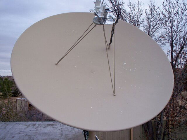
Being a well-manufactured solid prime-focus dish, my Birdview 2.6m (8.5') has the potential of being a Ku reception giant. I had tried in 2011 to achieve this using a modified dual ortho feed with an adaptor for a quad universal Ku LNB, using the original Birdview scalar as documented earlier in this thread. The dual ortho was always a problem child in its original form, and there is a separate thread for anyone interested in my mods. It did fairly well on the Birdview, but its Ku sensitivity was about 3 dB worse than one would expect from theory. That was better than its performance on all my other prime-focus dishes, which not coincidentally all have a lower f/D. My conjecture is the Ku part of dual orthos tends to under-illuminate prime-focus dishes, with a very ragged pattern over the frequency band. I have not bothered to prove this, but I have reams of evidence. I should also mention the C-band sides of dual orthos take about a 0.5 dB sensitivity hit compared to a single ortho feed.

When I last spent time tuning the 2.6m Birdview, my conclusion was it was an average performer on C-band, but its Ku performance with the dual ortho was no better than my 1.8m Prodelin offset with a dedicated Ku feed. Thus the Birdview was relegated to 24/7 58W C-band duty. My needs have since changed, and I now want a dish that outperforms by 1.2m offsets on Ku, without having to lock down my Prodelin. With no other free dishes left in the stable, I realized I could kill two birds with one stone by using the Birdview to fish out C-band at one orbital location, separated by 4 degrees from a Ku orbital location. Thus this project was born.

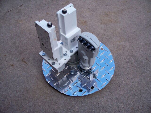
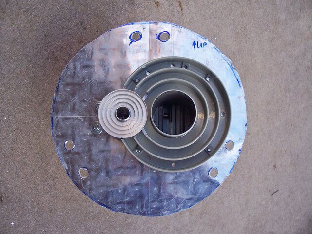
For those without a Birdview, these dishes originally came with a large C-band scalar (22.5 cm vs. a typical modern 16.5 cm), which is mounted by six struts to the dish. This scalar can be adapted to newer feeds as described above and in other threads. There isn't much more than can done to this device, and even less if one takes irreversible changes off the table (experiments are fine, but I like to be able to get back to where I was before). So I made a quick plan to make a feed mounting plate out of some flimsy aluminum, and configure separate and side-by-side C and Ku-band feeds. I liked the flimsy part because this way the mounting struts could twist the plate at the edge as necessary to line up. I tried this two different ways:

Try 1

As seen in the photos, I mounted a single ortho C-band feed and a Invacom ADF-120 prime focus Ku-band feed on the plate. Each was offset 36 mm from the center, and I used the LNBs from the Birdview's dual ortho. This required chopping out part of the C-band scalar to make room, and a small adjustment to move the Ku feed laterally (this is the experiment part). It would have been nice to have a similar adjustment for the C-band feed, but that is limited by the strut hole positions. Presumably I could have redesigned the feed mounting, but that wasn't interesting. By offsetting the feeds by the same amount, I could measure the sensitivity losses and compare the results to the dual ortho via measurements referenced from my other dishes.

This went on the struts easily, and having a bendable plate was actually kind of nice in tweaking the alignment, although crude. By the end of the day (actually after dark), I measured the C-band offset loss as negligible (< 0.25 dB), which actually meant the single ortho feed offset by 36 mm slightly outperformed a centered dual ortho (which starts 0.5 dB behind). On Ku I was seeing nearly a 2 dB improvement in CNR for the offset feed compared to the centered dual ortho. So the dual ortho lost both battles from the start. After that I moved the Ku feed further from center to achieve a 4 degree orbital separation between the two. This cost about a dB in loss, but I didn't spend a lot of time measuring that. By now I had realized I could start swinging for the stands.

Try 2

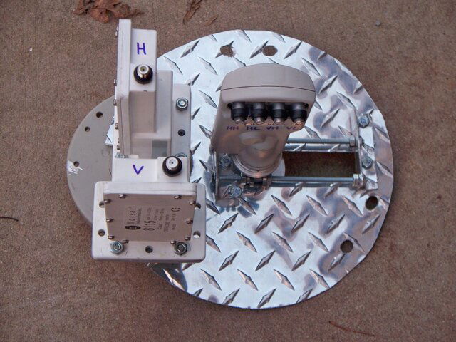
The next day brought about a new mounting plate with a different configuration. This time the idea was to center mount the Ku feed, because it had suffered a greater sensitivity loss than the C-band feed, for the same lateral offset. To achieve a 4 degree mounting separation, this forced the C-band feed past the edge of the mounting plate, which had been sized to match that of the original Birdview scalar/mounting plate. I knew this would be somewhat of a mess, because at least one strut would have to plunge through the C-band scalar, and drilling this would be a bit tricky. I was able to line up this plunge in between the scalar rings, but that caused the adjacent strut to nick the edge of the scalar. So I had to line up two plunges.

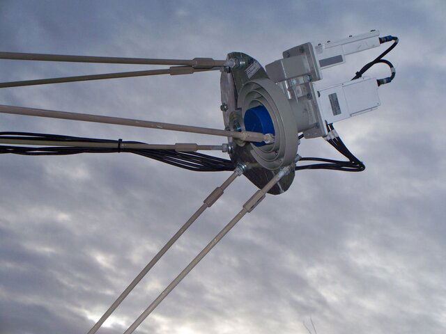
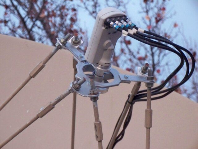
The performance of this plate is outstanding. I measured the centered Ku performance at about 3 dB greater than that of the dual ortho. In fact it is pretty much scaling theoretically, meaning the Birdview surface accuracy is exceptional. With the single ortho C-band scalar 4 degrees off-center, it experienced about a 0.5 dB offset loss from its position in Try 1, or roughly 0.25 dB worse than the centered dual ortho C-band performance. To me this makes the second plate a no-brainer. The feed-mounted pictures show the new configuration, and in particular the difficulties in dealing with the Birdview struts. Also, it may not be apparent, but the C-band feed is slightly canted inward with washers to improve performance in both Try 1 and 2.

For those into measurements, a 4 degree orbital spacing between the feed centers required about 95 mm of separation at the plate, slightly more than I had calculated. As many know, Birdview mounted their feeds about 25 mm too close to the dish, with no stock adjustment. I corrected this with strut modifications described earlier in this thread, and with the modern feed/scalar, a rough check indicated this was still the best position. I protruded the C-band feed 6 mm above the top of its scalar rings. The Ku feed was protruded 3 mm above the top of its scalar rings, which was about 1 mm below the top of the C-band rings.

Try 1 back.jpg Try 1 front.jpg Try 2 back.jpg Try 2 mounted.jpg The whole nine yards.jpg
 
Very nice work, congrats on your well-deserved success.

Great thread, had to reread the whole thing.

Maybe, someday, one of the near-mythical 9'-6 BV solid reflectors will become your new testbed. I located one within a few hours drive of you a couple years ago, way too far for me to pursue but let me know if you have an interest in it.
 
Thanks to everyone who liked my work.

phlatwound - I wish I could try the 9.5' solid Birdview, but my personal city ordinance would either cost me taking down two dishes mounted on my roof or replacing one of the two bigger C-band dishes on the ground. For the moment, neither sounds attractive. I'm hoping to make some kind of improvement down the road, but for the moment I'm staying mum.

ynnedibanez - the Ku side of the centered Birdview feed turns in CNRs about 3.5 dB more than the 1.8m Prodelin. This is a little better than the theoretical gain of 3.2 dB, assuming identical efficiencies. Measurements over the years indicate the Prodelin loses around 0.5 dB of efficiency compared to smaller dishes, which implies the Birdview is losing around 0.2 dB. These are both very small for a big dish, considering many people who run dual orthos on a prime-focus are losing > 5 dB on Ku, and those with a corotor lose even more (years ago I did a quick test of the corotor that came with my rather deep 3.2m mesh - its loss on Ku was about 10 dB). Realize that all of these numbers vary over the passbands, and I am trying to quote meaningful averages.
 
I'm resurrecting this ancient thread because of a couple of developments. The first is I've acquired another Birdview, and this motivated me to improve a few minor issues dating to my original install. The second was the failure of the rotary encoder in my first Birdview. Naturally I don't want to repeat mistakes on the #2. This post will address this second development.

The encoder failure was simple - water leaked into it rendering the sensor circuit inoperable. Although it took five years, I'd like to avoid such maintenance in the future. Thus I (1) caulked silicon sealant at the top edge of the mount (see picture), (2) drilled a couple of drain holes in the bottom plastic mount housing, and (3) sealed the edges of the new rotary encoder, where the water seeped in. This still leaves the encoder shaft exposed, but apparently no water got close to that.

15 Top Sealing.jpg


In the process I also investigated my hunch that there was minor slippage between the encoder shaft and the encoder coupling in my original implementation. Both of my Birdviews came with the original potentiometers, used as absolute position sensors. When I removed the one on my first Birdview, I ended up reusing the roll pin that had coupled the gear shaft to the potentiometer. The AMT102 encoders come with a set of color-coded, differently sized sleeves to couple the actual encoder to a shaft. I had originally used the orange sleeve, which has a diameter of 2 mm, roughly close to the 1/8" roll pin.

But this seems to be a weak link, because the sleeve is in two pieces. If the sleeve is a little too small for the shaft, the two pieces will pop apart, causing no coupling to the encoder. If the sleeve is a little too big, it will not completely grip the shaft and will slip. Years ago I chose to err on side of too small a sleeve, but over a long period of time, the counts on my controller tended to randomly shift by small amounts. So this time I tried the purple sleeve, which at 3.125 mm should be a perfect match to the roll pin. However that slipped like mad, perhaps because the original roll pin was only 0.5" long, and the sleeve was always on the verge of slipping off the end of the pin (see picture).

16 Shaft Issue.jpg


The next scheme was to build a bigger shaft. I purchased a 1.5" long 1/16" roll pin to first hammer into the gear shaft, and a 1.25" long 3/16" roll pin to hammer on top of it (see picture).
17 Roll Pins.jpg
This fit the shaft fine, but the resulting outside diameter didn't quite match the available sleeves for the encoder. In frustration I wrapped one thickness of electrical tape around the outer roll pin, and that made things close for the red sleeve (6 mm) - realize the outer roll pin expands somewhat when hammered on top of the inner. But then I was back to the two sleeve pieces popping apart again. In ultimate frustration I glued the two pieces together and onto the shaft (see picture). That was a keeper.

18 Encoder Shaft Assembly.jpg


Now at least I can duplicate this design on Birdview #2. Before that I am going to work out a better feed arrangement, because I will be exclusively using both of my Birdviews for Ku only. That will be a future post, however.
 
Nice work, always enjoy seeing your projects.

You may want to consider a polyurethane sealant at your metal-to-metal intersections. I have had a lot of experience with installing, maintaining and repairing leaks of/in industrial metal roofs and silicone will not handle the expansion and contraction and still adhere to any metal surface for very long.

Tremco is one brand I have had great success with for caulking gun application, as well as this stuff:

http://ersystems.com/products/sealants/h-e-r/
 
Thanks for the tip - once I have both Birdviews up I'll get a tube of polyurethane sealant and take care of both.
 
  • Like
Reactions: phlatwound
While waiting for the steel yard to fabricate a pole extension for Birdview #2 (same as described for #1), I've been working on improving the feed support system on #1, because both Birdviews will become dedicated Ku dishes. Previously #1 had a centered Ku-band feed and an offset C-band feed. I don't need the latter anymore, so I'm using #1 to prototype a multi-Ku feed setup for #2.

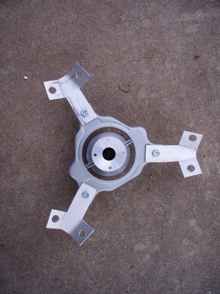
The first step was to get a centered Ku feed optimized on #1. After looking at many options, I picked up a couple of Ku feed mounts for prime focus dishes. These are called 'KU2C3" on the web. They're probably dimensioned for three leg supports that normally would attach to a C-band scalar. That doesn't match the six rod system on Birdviews, but as pairs of the rods closely intersect, it works out well. I cut three adapters out of 1/8" aluminum to join the KU2C3 mount to the rods. I've attached a PDF file that I drafted for a template, and there is also a picture of how these were bent and mated to the KU2C3, with the Invacom ADF-120 feed installed. The feed is held solidly, very close to center.

Before taking down the old center-Ku/offset-C feed mount, I measured the distance from the end of the Ku feed to the center of the Birdview as 1.023 m. I also calculated the focal point inset within the feed as 4.4 mm. Thus this was tuned to an apparent focal point of about 1.027 m, which was pretty close to my notes from when I installed the combined feed. I didn't measure it, but the Ku feed was slightly offset from center, because that was the only way I could adjust the Ku to C separation to match the orbital locations. I had been forced to fix the C-band scalar position because of mechanical interference from the Birdview rods as noted in an earlier post.

Even before this I knew the Ku feed was sightly offset, so a couple of weeks ago I wrote a 'coma calculator' program to model the spread of beams for satellites offset from the dish axis. For those not familiar, a parabolic dish (or mirror) can only bring all incoming parallel rays to focus when they are on axis. For any other signal source that is offset, rays reflecting off various parts of the dish will not intersect at a single point. However one can calculate a 'circle of least confusion' for a given feed where the maximum power can be captured. This tends to be more severe for Ku than C because of the relative diameters of the feed waveguides. To cut a long story short, several examples I ran suggested this circle of least confusion moves farther out from the focal plane (or point) as the offset increases.

There has been a lot of discussion over the years as to what the the focal distance actually is for Birdviews. The common belief is that the rods on factory-fresh Birdviews were cut too short, resulting in the feed being too close to the dish by about an inch. When I rescued my first Birdview I measured the C-band scalar rings to be 1.003 m (39.5") from the dish center. I then indirectly calculated the focal length by measuring the dish diameter and depth, coming up with a calculated focal length of 1.031 m (40.6"). Although this was imprecise because the outer portion of a Birdview dish is very clearly not parabolic, this was in the neighborhood of common belief to the point I accepted it. I should point out that the focal point is generally best tuned slightly inside a feed's waveguide. For the Birdview C-band feed I calculated this inset roughly as 16.4 mm (0.64"), which would put the factory-set rods placing the focal point at 1.0194 m (40.13"). Thus if my measurements and estimates were perfect, and I know they were not, the focal length discrepancy would be around 12 mm (0.46") instead of an inch.

So back to the present. The nice thing about this feed support is I can very precisely center and aim it with a laser ruler. I managed to get all three arms within 1 mm of the same distance, and the feed pointing at the center of the dish. When the collar is loose, it is easy to slide the feed in and out, and the ADF-120 scalar rings can be easily set to match the f/D of the dish by adjusting the cutoff at the dish edge. For the Birdview f/D of 0.403, this comes to a protrusion of the feed by about 2.5 mm beyond the scalar rings, according to Invacom. See the picture of everything on the dish.

I spent a lot of time tweaking the dish and finding the best focal length and feed protrusion. When all was said and done, the distance from the feed edge to the dish center was 1.006 m (39.61"), or an approximate focal length 1.0104 m (39.78") after adding the expected focal point inset of 4.4 mm for the ADF-120 with the Birdview geometry. This is interestingly LESS than what the factory rods will set, rather than more. Fortunately my Birdview #1 has adjustable rods, so this wasn't a big deal. However I will need to take this into account for Birdview #2, for which I was trying to avoid doing the adjustable rod modification. I also measured the best feed edge to scalar ring protrusion as 2.66 mm, which is very close to what Invacom shows on their graph.

Overall I've realized about a 1.5 dB CNR improvement, although because I did not do relative measurements against a reference dish, this a very rough figure. For the moment I'm inclined to believe the improvement was because I now have the Ku feed precisely aligned and centered, as compared to slightly offset with the combined Ku/C feed I had previously fabricated. This not only presumably brings the coma to zero, but also the circle of least confusion in towards the dish and at the focal point. Because I never measured the offset of the old feed mount, as it was very crude and imprecise, I decided to pass on trying to resolve the numbers from my earlier efforts with the new.

19 New Feed Mount.jpg 20 The New Deal.jpg
 

Attachments

Great update!

Are you saying the factory rods are closer to the correct depth then what people have been making them?
 
Hank - that seems to be the case - even I had jumped on the 'rods too short' train when I put up Birdview #1. But there are still several twists left in this story.

To determine where the focal point really is, one needs to know both the distance from the center of the dish to the feed's opening edge, and the inset distance from that edge to the actual best focal point position inside the waveguide. This inset distance is normally determined empirically, and I haven't seen a complete derivation from theory. I have come across approximations that don't seem to exactly match real world measurements. Also measuring these quantities is a rat hole, because it is difficult to get accurate enough measurements.

The original Birdview feed and scalar are quite a bit different from 'modern' feeds and scalars. Thus the focal point inset could be somewhat different that what we typically see on other feeds and dishes. I would not be shocked if this is part of the explanation.

Another possibility is that C-band is much more forgiving than Ku-band when it comes to large dish tuning. Varying the feed distance a little off the focal point will not cause as drastic a loss for C-band, and as far as I know, Birdviews like mine never came with dual ortho feeds from the factory. Where they put the feed may have been good enough, if not perfect.

What is useful in my latest measurements is I am optimizing exclusively for Ku-band, and small adjustments yield more easily measured CNR deltas. Today I could see the difference in varying the feed position by as little as 1 mm, and the protrusion of the feed beyond the scalar rings by as little as 0.1 mm. I sometimes get things wrong, but these results were pretty dramatic.

While I noted in my previous post that my latest results suggest that stock Birdview rods were too long, rather than the common view that they were too short, there is another line of reasoning that could apply. While I don't particularly trust the focal point inset approximations, I had little choice but to use them in determining where the presumed focal point was located, relative to the feed horn edge. That is the only thing I can measure. But these approximations calculate a C-band inset of 16.4 mm, which just seems too large for my gut. If this was less, the difference between my Ku-band focal point measurement/estimate and where Birdview put their C-band horn would start getting very close to the same thing.
 
... To determine where the focal point really is, one needs to know both the distance from the center of the dish to the feed's opening edge, and the inset distance from that edge to the actual best focal point position inside the waveguide. ...
On my Birdview, the center portion of the dish appears to deviate from a true parabola. I noticed that shortly after I got it when I applied mirror film to the surface in an experiment to make a powerful solar cooker (it set wood on fire quickly!). With the mirror film I could clearly see that the dish flattens out more than it should from the center out to about a 12 inch radius. The center section of the dish deviates from a true parabola. So the "effective" depth of the dish is slightly greater than a measurement from the center surface to the rim would indicate

This would explain why previous calculations of the focal length based on the observed depth and width were too large -- the dish is deeper than it appears.
 
My Birdview is the same, the center 12 inches or so flattens out. Not really an issue with the original large C Band scalar, as it would shade this area. But as you said, it would throw off the measurement of the depth.
 
On the surface these appear valid points. However a parabola is quite flat near its center. Since Birdview #2 is on the ground, I took a 12" ruler and placed it across the center of the dish. Now the center 2" of a Birdview is open and normally filled with a plastic hole plug, so I had to measure the depth at a 1" radius using a caliper, which was roughly 0.18". This corresponds to depth difference from a 6" radius to a 1" radius. Based on my 2011 notes, I would expect the parabola to have a depth difference of 0.22" between these points, which is 0.04" more than I measured. But this represents a flattening of only about 1/32" (or 1 mm), if my measurements today were highly precise. Which I doubt. Instead I'm inclined to say that the dish is actually pretty accurate starting at a radius of 1".

Because of the center plug and the fact that the outer rim of the dish is rolled (clearly deviating from a parabola), back in 2011 I tried a couple of techniques to estimate the diameter and depth of the dish. One was to string a wire tight across the dish and measure the depth at several distances. My recollection was that a parabolic fit was pretty good up until one approached the dish edge. This helped me in determining the effective diameter of the dish, and I measured the depth at a 1" radius because of the center hole. My calculated f/D was 0.403 vs. Birdview's spec of 0.4, virtually identical.

Unfortunately this flattening effect could only account for a 1-2 mm difference in the calculated vs. measured focal length, and very possibly less. Instead this morning I tried once again to bring Birdview's numbers and mine into correspondence. From my 2011 measurement, the original Birdview scalar rings were 1.003 m from the dish center. Just for laughs, I'll guess the focal point inset for the Birdview feed to be about 1/4", which isn't an unusual number in practice for my other C-band dishes/feeds. If these numbers are correct, Birdview would have been designing a focal length of about 1.009 m (39.72"). Yesterday I measured the distance from my Ku feed opening to the dish center as 1.006 m. Using a proportionality scaling between Ku and C-band, I would calculate a focal point inset of 2 mm for the ADF-120 feed. That yields a focal length of 1.008 m (39.69"). While I've mixed fairly accurate measurements with some gut, this could be very close to fact.
 
Status
Please reply by conversation.

Users Who Are Viewing This Thread (Total: 0, Members: 0, Guests: 0)

Who Read This Thread (Total Members: 3)

Top