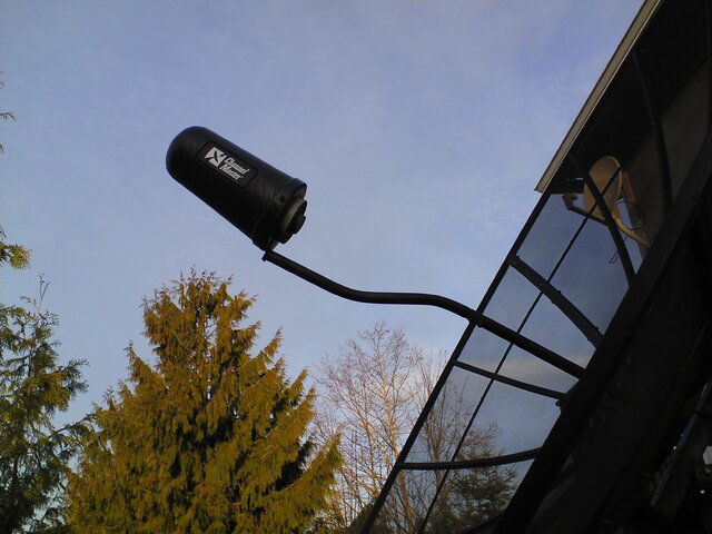
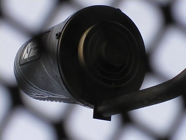
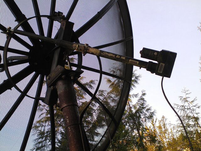
Is there a cover on the feed horn?If not wasps think that is a swell place to build a nest and keep the probe from turning.
Need wiring help with Echostar 4000 SRD C-band receiver
- Thread starter be236
- Start date
- Latest activity Latest activity:
- Replies 46
- Views 8K
You are using an out of date browser. It may not display this or other websites correctly.
You should upgrade or use an alternative browser.
You should upgrade or use an alternative browser.
- Status
- Please reply by conversation.
Ok, assuming the color mappings are correct as you stated...
I found my remote control and when I tried to switch to another satellite, I would hear a click from the receiver (which was normal me I did this).. but then the SRD-4000 would give me E-14 error on display, which means "motor limit reached."
I tried to reset the receiver to "defaults," but still I get this error.. ideas?
OK; the receiver needs a "mind" reset; as the battery when it goes un-used for a year or more will make the mind fuzzy; and E14 can be this. But I see another problem; you have no cable going between the analog 4000 and the motor controller box; a heavy smaller box with a plug connector that goes between the receiver and the power supply box. The 4000 did hook polarity powers directly from it to a stationary dish. E14 means also the cable is not hooked between the two (2) box set. It basically looks the same as a GI 2000? two (2) box set using the same "an old houston tracker cable will work" 8-pin type plug cable?4 pins were ???) and a GI power supply...and the motor wires and pol. wires? then go to this box instead...but the plug connector hooks between the two boxes to control both or one of these satellite selections of forward/reverse pol. and east west controls.
Also, the 4000 models in the newer era of its lifetime did have powers for the motor builtin and FATAIR is correct...
but yes, i do have a GI power supply availlable; for controlled C Band motors...and it works with a gi or a echo 4000 (and my old PC)...
Also, the 4000 models in the newer era of its lifetime did have powers for the motor builtin and FATAIR is correct...
but yes, i do have a GI power supply availlable; for controlled C Band motors...and it works with a gi or a echo 4000 (and my old PC)...
Last edited:
Is there a cover on the feed horn?If not wasps think that is a swell place to build a nest and keep the probe from turning.
yes, there is a cover on the feedhorn... I will try to take a picture of the feedhorn and actuator when I get a chance... The actuator I can get too via ladder. but the feedhorn is in the middle of the dish mesh and not sure how to access it w/o stepping into the mesh dish itself...
Ok, I will try to reverse the motor wires next... and are you sure the sensor wires are correct/colored too?EDIT: reverse the motor wires and try again
If still error:
Now you're going to need a battery to see if the actuator works.
But first, take the back cover off and inspect it for water infiltration.
And check the wires for continuity.
OK; the receiver needs a "mind" reset; as the battery when it goes un-used for a year or more will make the mind fuzzy; and E14 can be this. But I see another problem; you have no cable going between the analog 4000 and the motor controller box; a heavy smaller box with a plug connector that goes between the receiver and the power supply box. The 4000 did hook polarity powers directly from it to a stationary dish. E14 means also the cable is not hooked between the two (2) box set. It basically looks the same as a GI 2000? two (2) box set using the same "an old houston tracker cable will work" 8-pin type plug cable?4 pins were ???) and a GI power supply...and the motor wires and pol. wires? then go to this box instead...but the plug connector hooks between the two boxes to control both or one of these satellite selections of forward/reverse pol. and east west controls.
Also, the 4000 models in the newer era of its lifetime did have powers for the motor builtin and FATAIR is correct...
but yes, i do have a GI power supply availlable; for controlled C Band motors...and it works with a gi or a echo 4000 (and my old PC)...
My SRD-4000 unit is self-contained... my setup is just the dish itself , the wires to the receiver, and the receiver itself... there has never been any external power supply or motor unit to this receiver, when it worked 8 years ago, before I disconnected the wires and cables and stored the receiver away.
And it should still get an analog channel; like F3 CSPAN>... The motor wires hooked up to the unit before? The dish has a motor already; and it worked; then where the two big wires (larger motor wires) should be able to move the dish. The way it works to check their voltages is to hook a volt meter to the two east west motor lugs on the receiver; and go east or west with the remote; the e14 will show; and the meter will show a brief 24-36 vdc +- on the meter. If you continually put a pulse train (touching a wire between the two pulse or sensor connections) then the 24-36 vdc will stay on while you make up a continual count to it (motor supply). Normally, Also, if at anyrime the two sensor wires have been plugged into a wrong lug or even touched to a wrong log while unit is plugged into electric 120vac; (12 vdc is the 3rd lug and big trouble) then the sensor on your motor outside will blow (they are normally 5vdc reed sw). Otherwise, E14 means no pulse is being received by the receiver and the wire going to the dish must be checked for continuity; or if they are shorted by mouse; vermine; man; no pulse can mean the cable between the dish and receiver is shorted or open...if the motor is bad or the cables to it are shorted or open; e14My SRD-4000 unit is self-contained... my setup is just the dish itself , the wires to the receiver, and the receiver itself... there has never been any external power supply or motor unit to this receiver, when it worked 8 years ago, before I disconnected the wires and cables and stored the receiver away.
SRD = single (satellite? or one (1)) receiver (digital audio) - I mostly worked on a 5 foot dish with a pr1e aimed at G1 (for galaxy one had all the dish needed; no motor needed). But then; the SRD4000 changed into motored dish type (like a houston tracker); and had a power supply box seperate. Then it got built into the SRD4000; and the motor lugs worked (but were not hooked up in the older SRD4000).
This was also about the time Echostar sent modulus to Mexico; and a deal was made (the plane crashed and mystery is what or why it did, pilot was doa and the 1000 modulus burnt up).
Last edited:
opening the motor up to expose the connections will tell. (but I'm 99.9% sure I'm correct) If I'm wrong oh well.Ok, I will try to reverse the motor wires next... and are you sure the sensor wires are correct/colored too?
As a side note: You can remove the DCII module. (plastic affair right below the motor screw terminals. Just wiggle it out) Battery is probably dead. and there's only one channel up there, but getting a subscription to it is a no go. So now it's just another unnecessary load on the receiver's power supply.
opening the motor up to expose the connections will tell. (but I'm 99.9% sure I'm correct) If I'm wrong oh well.
As a side note: You can remove the DCII module. (plastic affair right below the motor screw terminals. Just wiggle it out) Battery is probably dead. and there's only one channel up there, but getting a subscription to it is a no go. So now it's just another unnecessary load on the receiver's power supply.
Yes, I can remove the VC2 module from it just fine. Actually I could not find any analog / NTSC signal channel at all, remember, I am stuck on V polarity on 121 W.
Yes, the cable/wires and the receiver are all original. This setup worked 8 years ago before I disconnected the receiver and wires from it. I didn't touch any wires to the dish itself.And it should still get an analog channel; like F3 CSPAN>... The motor wires hooked up to the unit before? The dish has a motor already; and it worked; then where the two big wires (larger motor wires) should be able to move the dish. The way it works to check their voltages is to hook a volt meter to the two east west motor lugs on the receiver; and go east or west with the remote; the e14 will show; and the meter will show a brief 24-36 vdc +- on the meter. If you continually put a pulse train (touching a wire between the two pulse or sensor connections) then the 24-36 vdc will stay on while you make up a continual count to it (motor supply). Normally, Also, if at anyrime the two sensor wires have been plugged into a wrong lug or even touched to a wrong log while unit is plugged into electric 120vac; (12 vdc is the 3rd lug and big trouble) then the sensor on your motor outside will blow (they are normally 5vdc reed sw). Otherwise, E14 means no pulse is being received by the receiver and the wire going to the dish must be checked for continuity; or if they are shorted by mouse; vermine; man; no pulse can mean the cable between the dish and receiver is shorted or open...if the motor is bad or the cables to it are shorted or open; e14
SRD = single (satellite? or one (1)) receiver (digital audio) - I mostly worked on a 5 foot dish with a pr1e aimed at G1 (for galaxy one had all the dish needed; no motor needed). But then; the SRD4000 changed into motored dish type (like a houston tracker); and had a power supply box seperate. Then it got built into the SRD4000; and the motor lugs worked (but were not hooked up in the older SRD4000).
This was also about the time Echostar sent modulus to Mexico; and a deal was made (the plane crashed and mystery is what or why it did, pilot was doa and the 1000 modulus burnt up).
Also, I am stuck on 121W and I don't see any analog channels. But if I hook upmy MPEG2 receiver, I get this BON and RT Esp as listed in Lyngsat.:
3780 V
tp 4
C
41-43

781-4096
7.2
P Parente
160106
Blue Ocean Network

112 3120 3121 E
3122 E
RT Español


113 3130 3131 Sp
3132 Sp AC3
So I know I am stuck on V polarity for now.
I do have voltmeter to measure any leads/connectis you want (see my prior screenshots).
You could mark the feed throat/scalar relationship, then rotate the throat 90° to get on Horizontal for now. IK-PIB.
Check continuity of the motor and sensor wires. 8yrs, water could have corroded them to mere oxide.
.
Are you talking about the wires at the actuator itself, I assume.. not the feedhorn wires (it's got a cap so I can't see any wires sticking out of it).
Once you get the actuator working,you should be able to move the dish to a position where you can reach the feed horn.yes, there is a cover on the feedhorn... I will try to take a picture of the feedhorn and actuator when I get a chance... The actuator I can get too via ladder. but the feedhorn is in the middle of the dish mesh and not sure how to access it w/o stepping into the mesh dish itself...
Once you get the actuator working,you should be able to move the dish to a position where you can reach the feed horn.
Ok, here are the picts of feedhorn and actuator. All looks intact, albeit worn/dirty.
Attachments
Yes, the cable/wires and the receiver are all original. This setup worked 8 years ago before I disconnected the receiver and wires from it. I didn't touch any wires to the dish itself.
Also, I am stuck on 121W and I don't see any analog channels. But if I hook upmy MPEG2 receiver, I get this BON and RT Esp as listed in Lyngsat.:
3780 V
tp 4
C
41-43Level 3 DVB-S 29270-7/8
781-4096
7.2
P Parente
160106
Blue Ocean Network
112 3120 3121 E
3122 E
RT Español
113 3130 3131 Sp
3132 Sp AC3
So I know I am stuck on V polarity for now.
I do have voltmeter to measure any leads/connectis you want (see my prior screenshots).
From my experience; now that a thread had been written; i am a sorry typing in "did not see it work" "oh, baby you have a holy grail" of satellite tv; and it works already! Yay.
The working model of satellite tv is a motor controlled dish. The LNB has a working 18 vdc supply; the splitter feeds the DVB-S2 receiver; the coax is the only working part and is on 1 satellite -121 C Band and is receiving the channels ;
the parts to motorize are as follows and provided in this thread: the bracket can be moved (loosened/slid/locked back tight) to go to other satellites
1-check wires to/from motor - unhooked all shorted then all open and seperate from each other unhooked (both that the wires are not shorted to each other or not continuos) lites (voltage checkers) can do this
2-check wires to/from PR1e - same
3) check parts removed from wire (motor and polarotor); check receiver for correct voltages w/o wires hooked; both multi-meter and even hookup to analog directly w/o existing wire
This will completely test, and determine what needs repair or not. If the motor is jammed and only needs alota' grease is the fix for them (take them apart and put them back together again. Polarotors also get jammed againgst buitl-in stops inside of themselves; and can be un-jammed also.
Additionally, channel's in a dvb-s2 receiver; can make everything auto-magic again by installing a DISEqC controller and a C or C+Ku LNBf as well as the cables continuity for the motor needs repair or not. These parts must be installed to replace the electronics last; but add better control for the newer "digital" mindset tv today has gone to.
Just tickle the wires to the battery. If it's sized up you don't want to damage anything. A few screws should remove the cover and expose the drive off the motor and limit switch. Good luck.
Sent from a phone, probably while I'm driving over the speed limit through a school zone with construction workers present.
Sent from a phone, probably while I'm driving over the speed limit through a school zone with construction workers present.
- Status
- Please reply by conversation.
Similar threads
- Replies
- 21
- Views
- 1K
- Replies
- 2
- Views
- 243
- Replies
- 9
- Views
- 1K
- Replies
- 3
- Views
- 792
- Replies
- 1
- Views
- 357


