Need SatelliteGuys Assistance for C-band Feedhorn Alignment Tool Project

Status
Please reply by conversation.
When you mention dual ortho are you refering to a Bullseye?..I can take measurements there also.

So many variables with this.The one thing I ran into with this same project here was finding a laser that was true ( perpindicular ) to it`s outside diameter..Curious what laser is in mind?..Even tho we are dealing with castings I do think a fixture can be made with a high precision rate but the laser is in question?

#4 is important and true centering of the scaler.
 
Hockeynut, I was referencing this post for the 2.25". Not sure what model.
My Chaparral dual ortho ID is 2 8/32'' at the feed entrance and the same all the way down.

Working with a laser product manufacturer that has hundreds of hardware build solutions, both packaged and at component level. They have the capability to cast and calibrate as they provide laser solutions for a major tool company that we all know. Looking to use an existing pre-assembled self-contained laser module which is used for manufacturing a torpedo level and cast it into the final form.
 
  • Like
Reactions: ZandarKoad
If the assembly is to be recessed in the throat (may be your best choice), you will have to have a relief cut into it to give clearance for the Cband probe. As stated before on a corotorII the end of the probe is almost flush with the end of the feedhorn (only enough clearance to prevent interference with a feedhorn cap). The butterfly that rotates with the probe measures 1.125 inches corner to corner. Allow at least 1.250 inches to be safe.

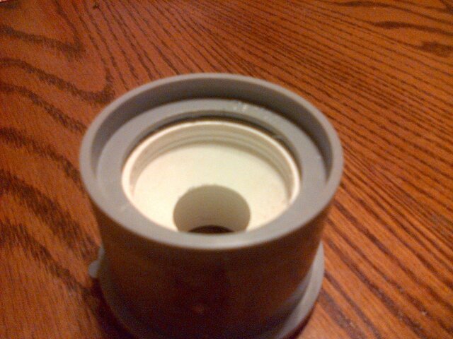
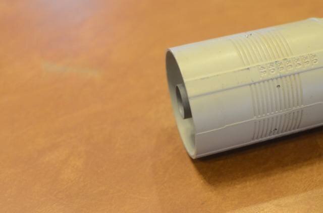
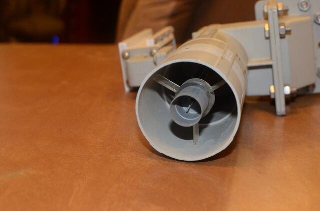
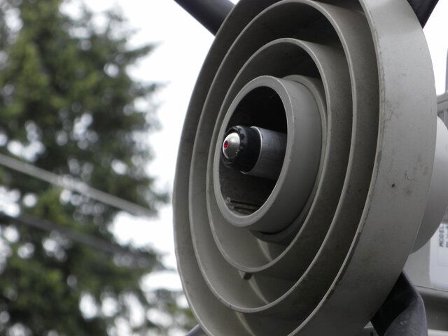
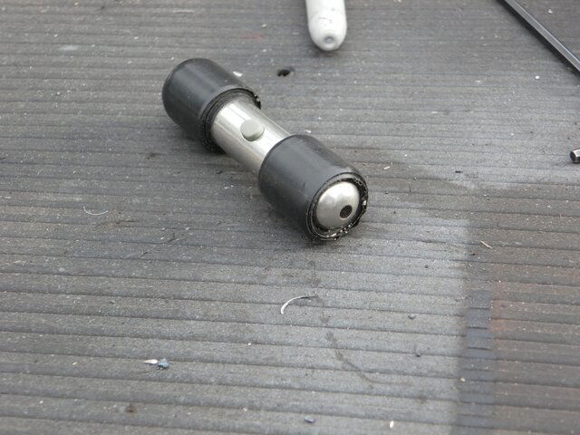
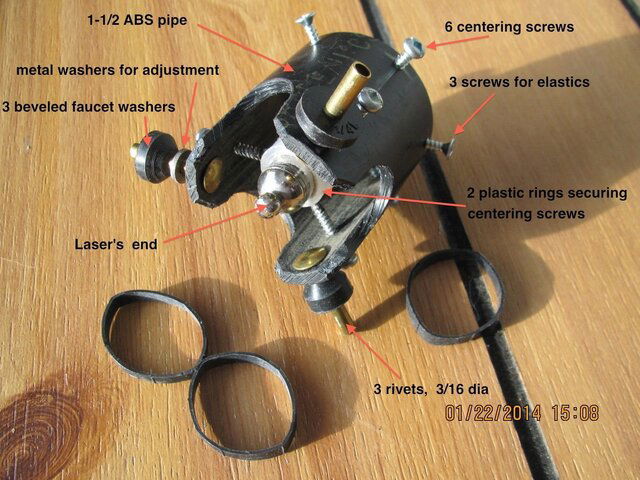
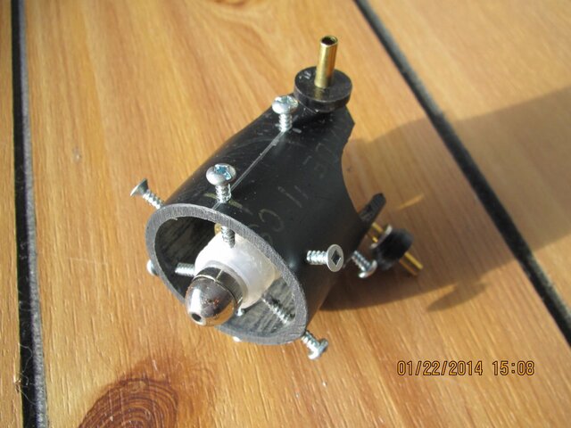
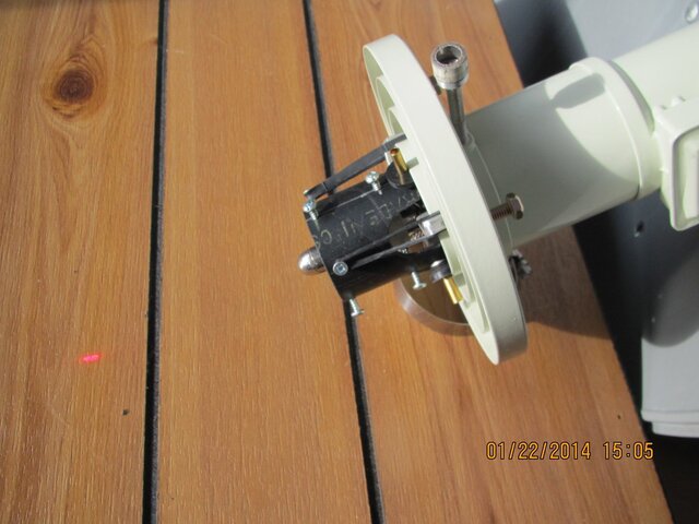
I made up a crude alignment tool for my own feedhorn using pvc fittings and a laser pointer. Because the laser was not precision I mounted it in a threaded nipple so that I could rotate it (instead of a dot I had a small circle) to find my center. I've attached a picture of the backside to give you an idea. This tool could safely be recessed into the throat .750 inches.
 

Attachments

  • 004.jpg
    004.jpg
    527.6 KB · Views: 303
Last edited:
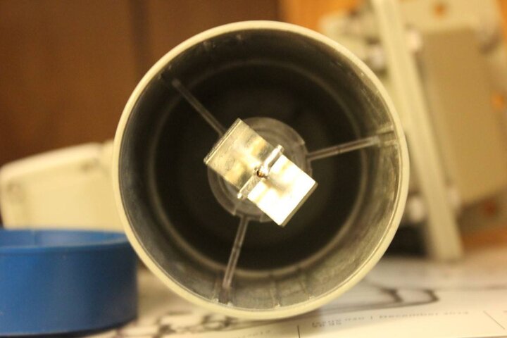
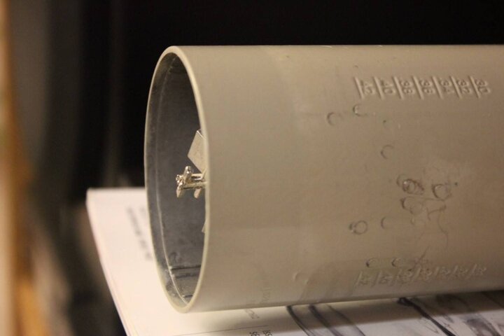
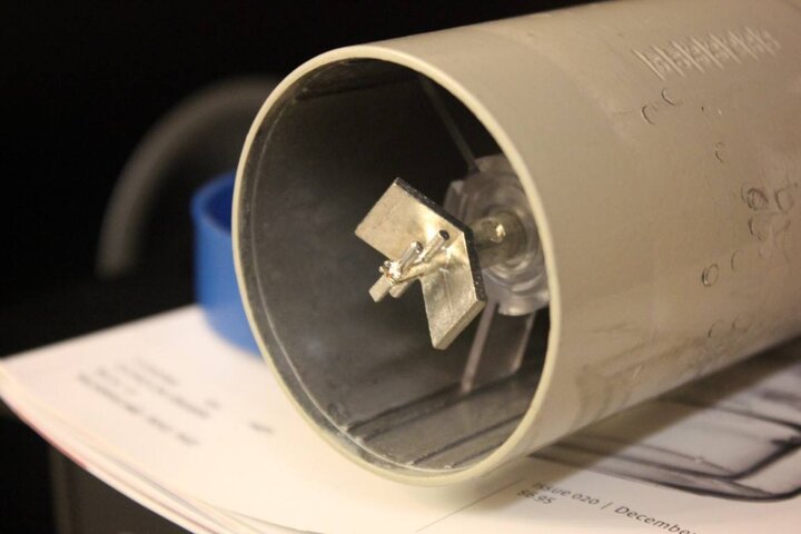
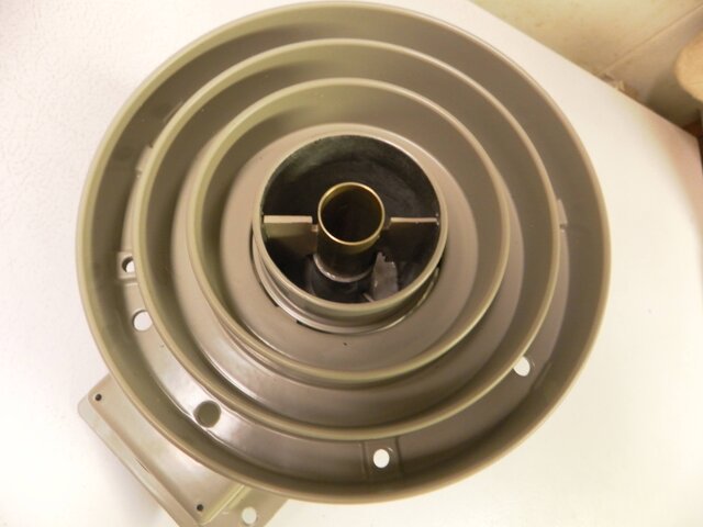
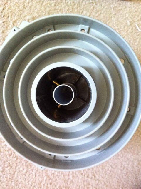
The Chapparall Corotor Ku probe is very close to being flush with the feed horn opening. The alignment tool would have to attach to the outside diameter, unless it has three fingers that adjust to fit between the probe centering web. We don't want anything touching the probe either.


IMG_2187 (Medium).JPGIMG_2186 (Medium).JPGIMG_2185 (Medium).JPG

Didn't get measurments, my caliper set is in the toolbox in a truck parked in a shed that is almost buried in snow... Will have to wait a day or two before digging it out, blizzarding here right now. :(

-C.

edit
measured with ruler, ID at opening is 2 7/16", OD at opening is 2 9/16", that is as accurate as I can get with the ruler...
 
Last edited:
Brian,
If you decide that the unit will clamp to the front there should be a way to visually or mechanically insure that it is centered in the opening and it would be nice to have a switch on the face of the unit to turn it off while your looking for the screw that you just dropped into the tall grass.
 
To recap the thread so far:


It appears that the Chaparral Dual Ortho feed has the smallest ID measurement at 2.25. What is the OD measurement of the Chaparral Dual Ortho taken at the entrance? It seems like it would be much smaller OD than other feedhorns.


:D

Brian, disregard this measurement, pretty sure it's wrong. Just went to double check the OD on the ortho for you and noticed the calipers are acting wonky. They're a very old mechanical pair with the dial that I've had for years and don't hardly ever use anymore, so it's no surprise they've finally sh.. the bed. Gonna pick up one of those $20 something cheap digital calipers this weekend and then I''ll redo all my measurements.
 
there should be a way to visually or mechanically insure that it is centered in the opening and it would be nice to have a switch on the face of the unit to turn it off.
Seating the unit over the feedhorn rim then securing a clamp would likely provide adequate feedback as to if the unit was sitting flush. Not sure if the peepholes could be easily incorporated but we will throw the idea into the hat. The switch will likely be on the back of the unit as I am trying to keep the development cost reasonable by using a production run laser module with 2 x LR44 batteries.


What's the street price you're shooting for, soldier, for your new laser alignment tool ?
Targeting MSRP $30 - $35
 
  • Like
Reactions: ZandarKoad
I have a couple of pictures of my Chaparral Corotor that appears to be different than those already shown, in that the probe comes almost exactly to the front of the housing. I believe there have been adequate dimensions given, but if you need any more, please let me know.

DSC_6005.jpgDSC_6009.jpg
 
The KU tube on a new Bullseye II actually protrudes past the opening about 1/8". On the "Wideband" circular configuration the KU tube is glued in place. On the Linear one the tube with ku section is easily removed/ backed out of the way.
 
The KU tube on a new Bullseye II actually protrudes past the opening about 1/8". On the "Wideband" circular configuration the KU tube is glued in place. On the Linear one the tube with ku section is easily removed/ backed out of the way.

I don't recall seeing this new Bullseye II design. Do you have a photo? Would an additional 1/8" ooset provide clearance for the fixed wideband KU tube?
 
When I bought my second Bullseye, I got one new in the box but it was a "Wideband" circular C-Band model. I took a few pics to show the sender what the difference was. However it doesn't show how the Ku tube sits compared to the C-Band tube. I used a laser pointer wrapped with tape to fit the Ku tube when I set up that dish. I think an 1/8" would be fine.
bullseyeII 003.JPG feedbottom.jpg
 

Attachments

  • CMinstall 010.JPG
    CMinstall 010.JPG
    730.8 KB · Views: 312
  • CMinstall 009.JPG
    CMinstall 009.JPG
    1.8 MB · Views: 333
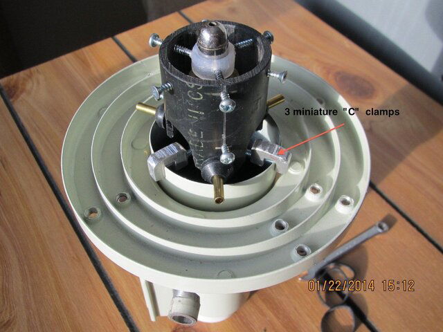
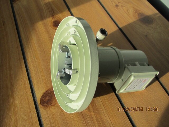
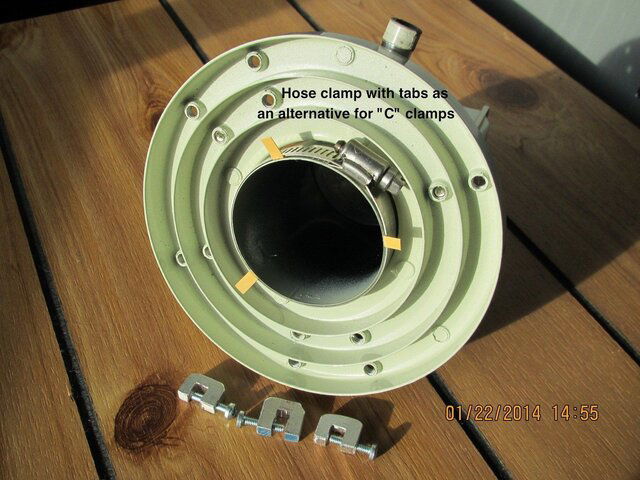
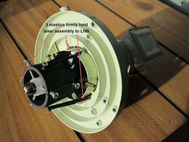
Laser holder made of plastic pipe

There are some ideas, perhaps worth implementation? Seven pictures follow
IMG_0888.JPGIMG_0889.JPGIMG_0892.JPGIMG_0880.JPGIMG_0881.JPGIMG_0885.JPGIMG_0887.JPG
 
Brian,
When setting up to mill, sometimes i simply take a very bent rod and chuck it in. then by spinning the mill as i bring the table up to it, i can see and measure if i am tipped at all to the table. an optic that spun in the lnb hole, would draw the outline of the dish in either round or egg shape also assisting in letting you know if you are square and centered to the dish. something like a laser pointer adjustable to find the edge of the dish and then spins such that it follows the outside of the dish. can be combined with a centering optic to hit both at once. I you draw an egg shape on your dish, the scalar is tipped or the dish is bent. kill 2 birds with one stone.

Kodaz
 
  • Like
Reactions: ZandarKoad
Here's new measurements on my feeds, Brian.

My Chaparral dual ortho ID is 2-7/16'' at the feed entrance and the same all the way down. At 2 15/16'' down the throat a plastic rod sticks out. The OD is 2-19/32''.

The Chaparral single, C only, polarotor-servo type feed has an ID at the throat entrance of 2-7/16'', at 1 1/2'' down it steps in 5/64''. The depth to the probe is 3 7/8''. The OD is 2-19/32''.

The National ADL single, C only, polarotor-servo type feed has a ID at the entrance of 2-5/8'', at 3/4'' down it steps out into the throat 7/64'' and then at 1 1/2'' down it steps out 3/16''. The depth to the probe is 2 7/8''. The OD is 2-29/32''.
 
Thanks everyone for the measurements, suggestions and sharing your projects. Your laser alignment devices are very innovative!

This information has been very helpful in designing a more universal solution for the laser alignment tool. Collaborating with a very talented CAD Satelliteguys member and we are making great progress on the project. Should be able to have manufacturers input after the Chinese New Year and put the project to bid.

We are working on an external clamping design with laser XY axis user adjustment. The projection will be either a cross-hair or dot.

A circle projection is a good idea, but cost consideration would require the size to be fixed with careful consideration to the size selection. A circle projection would be effective on solid reflectors, but not so much on mesh. I question the assertion that the circle shape would have significant or noticeable variance when the feedhorn is mechanically positioned. I can't imagine the shape noticeably distorting when the feedhorn movement is several inches and projected 50x+ distance onto a parabolic surface.

Mechanical and equal distance measurements from the center of the feedhorn to multiple points around the reflector rim is the traditionally the most accurate means to mechanically center the scalar/feedhorn above the reflector.

Another method using a feedhorn laser would be to stretch two lines across the reflector face, edge to edge on the horizontal and vertical axis' of the reflector. Mark each line at the exact half diameter point and be sure that the two lines intersect at exactly these two marks. Position the laser in the scalar and strike this intersection point. The center of the reflector should be exactly shadowed by the intersecting horizontal and vertical lines. If the line shadows are not centered on the reflector, the feedhorn would need to be repositioned.
 
The CAD is completed thanks to the excellent design skills of a SatelliteGuys member. Currently shopping to determine a cost effective production method. Short run production will greatly exceed the target MSRP.


Brian Gohl
Titanium Satellite
 
Brian,
Great idea. How about instead of a laser pointer, use a telescoping probe/ruler with a magnetic disc at the end to help hold it in place on metal dishes, make it reversible with non-slip surface on one side to help keep it positioned while you measure. This would give you the ability to center, and also measure focal distance, AND, if you include a cheap angle finder that can also be attached to the center probe, you can check your dish angle too! All of that should be as cheap as a laser and not require any batteries to mess with...except maybe one for the angle finder attachment.

Hope you can follow my thinking, let me know if I need to clarify/explain anything better.
 
Status
Please reply by conversation.

New to the Fta world

FCC Freezes C-Band

Users Who Are Viewing This Thread (Total: 0, Members: 0, Guests: 0)

Who Read This Thread (Total Members: 8)