I have started to lay out this project. I went through my parts bin and ordered some parts I didn't have. Thinking ahead I need to program this PIC. I don't have a pic programmer. And I have to learn how to do this with the ASM an HEX provided. So does anyone have suggestions as to what hardware/software to use for this project? Just point the way, I should be able to figure it out  I hope
Neat adaptation of my Corotor polarity/skew control
- Thread starter N0QBH
- Start date
- Latest activity Latest activity:
- Replies 66
- Views 14K
You are using an out of date browser. It may not display this or other websites correctly.
You should upgrade or use an alternative browser.
You should upgrade or use an alternative browser.
- Status
- Please reply by conversation.
Here is a neat one to start with. Works good if you have an actual RS-232 card in your computer. You have have put it together yourself, but you will learn more about PIC's. I have never owned it, but have seen it recommended several times in the past.
Amazon product ASIN B000LQDK3C
Amazon product ASIN B000LQDK3C
N0QBH recommended me PicKit3 to write HEX to PIC16F716 .
http://www.ebay.com/itm/PICkit3-Mic...656?pt=LH_DefaultDomain_0&hash=item4d28bab9a8
http://www.ebay.com/itm/PICkit3-Mic...656?pt=LH_DefaultDomain_0&hash=item4d28bab9a8
This is going to be fun. Since I will be adding this circuit to a VBox, I will also modify the design to use an existing +5V source from the VBox.
For a case I will use a dead ASC1 gen1 unit I have. I found some 1/8" thick 3 1/2" wide aluminum strap. A 7 1/2" piece will make a new front panel and a 6 3/4" piece will replace the rear panel. But I will probably use the existing rear panel if the connections are in the right place.
Brian at Titanium has already named this box I'm in early stages of development and hope to post some pictures soon
For a case I will use a dead ASC1 gen1 unit I have. I found some 1/8" thick 3 1/2" wide aluminum strap. A 7 1/2" piece will make a new front panel and a 6 3/4" piece will replace the rear panel.
Brian at Titanium has already named this box
Update: I'm waiting for some circuit boards and the PIC programmer. I chose the "build-it-yourself" programmer as I can't resist that kind of deal  I have the rest of the components and have been working on the new front panel. I cut, drilled and tapped the piece of aluminum. Test fit the components and so far I'm happy. I need to find a better knob for the skew control
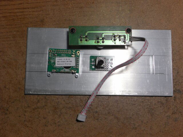
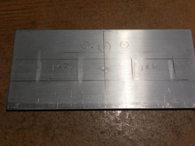
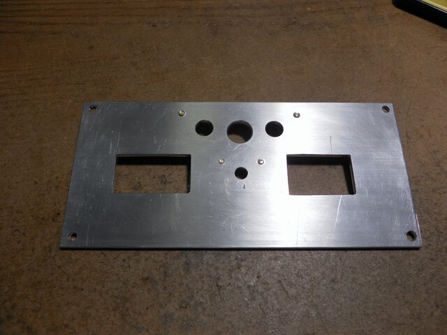
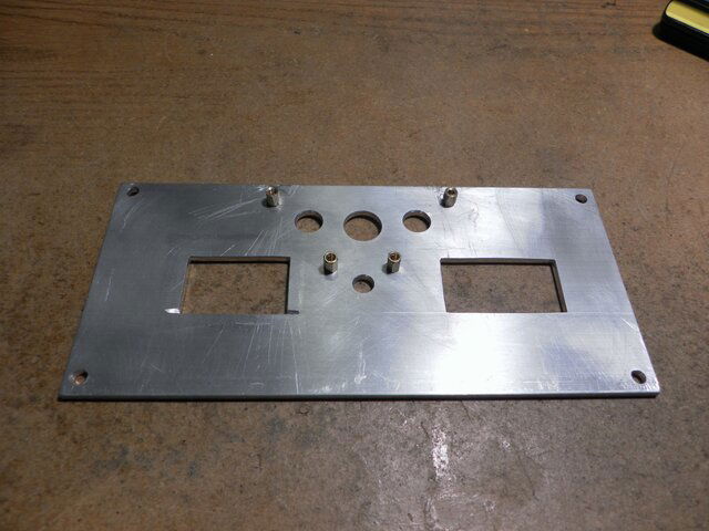
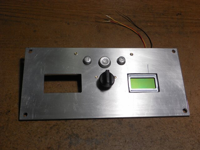
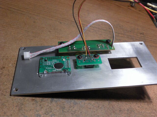


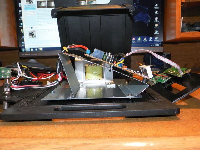
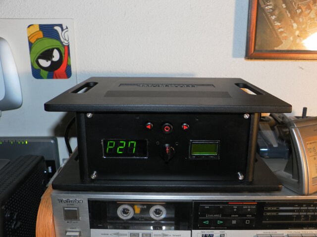
ASC1 gets a brain transplant and the "Franken-Box" is born. A few people have worked with the VBox 7 and it has some challenges when modifying the design. The VBox X I'm using has some different challenges. The main one is the LED display. It's unique "flying saucer" shape had the display mounted to the PCB at a 45° angle. And quite rigid too. I could stand it up only about 15° more. I ended up mounting the board into the case at an angle to get a good view of the display. I'm eager to get the circuit built. Seems like I'm doing this backwards. 
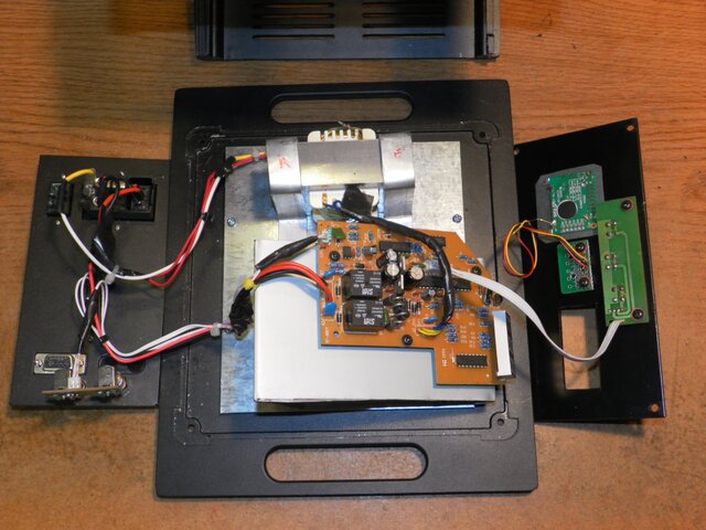


I'm a tinkerer and hobbyist, so I appreciate that you are putting a quality case to use.
Frankenstien got his parts somewhere...
Frankenstien got his parts somewhere...
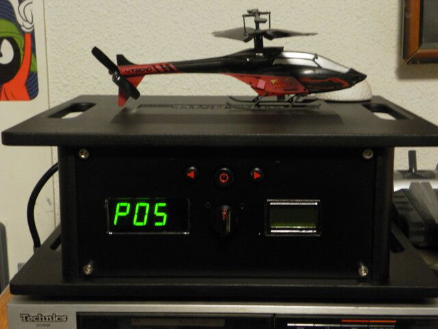
The POSThe helipad,or the P O S
The POSThe Helipad is part of a new dish security system. There is a harmonic sensor in the LNB array. It's tuned to the vibrations of a yellow jackets wing beats. When the sensor detects the presence of the infesting horde, the chopper is dispatched and the offending pests are destroyed. Still in development, you might say I haven't got the bugs worked out of it


I think I picked the wrong programmer  At least the PIC I need programmed is not in the list of PICs the programmer will do. Unfortunately the programmer doesn't come with a manual and the product info on the web site doesn't match the software and programmer I'm using. Since I am not familiar with these procedures, I'm kinda stumbling around in the dark. The programmer came with a blank PIC, but no hex files to write to it. Steep learning curve ahead . I need to find the correct manual for this programmer. This thing has experimental features I'll never use. You would think they would supply some kind of information with the kit
  I guess I should have heeded that notation "Programming experience required" I have flashed some chips before, but nothing as complicated as this unit.
Found another chm file in the programmer software folder for the programmer I'm using. The file that doesn't load up when you hit the help button  The software has a built in compiler. This part does list the 716 chip. But when I run the asm file it finds 74 errors. lol, I'm sure it does. To bad I can't just plug into the "Matrix" and upload the knowledge I need
  "onward thru the fog"
Yes, get this train on the track and it goes places  I've programmed my first PIC (16F627) with a utility to test the programmer and all is good
  There may be light at the end of the tunnel.
The light at the end of the tunnel was another train.  The Velleman programmer can not program the 716 chip
  It does a real fine job on many others though. I'm looking at programmers again with a more discerning eye
 The Velleman programmer can not program the 716 chip
 I use both the PICkit 3 mentioned by riz-la in post #23 and the CanaKit USB PIC Programmer.
Amazon product ASIN B004GRO52C
Both support the 16F716.
The CanaKit is kind of pricey, but has ZIF sockets, plus a plug (but no provided cable) for In Circuit Serial Programming. It looks like a PICkit 2 to MPLAB, so is plug and play.
With the PICkit 3 you will have to add a 6 pin header to your project to do In Circuit Serial Programming. Not a big deal.
I was wondering what the connection would be using that one. Thanks for the infoWith the PICkit 3 you will have to add a 6 pin header to your project to do In Circuit Serial Programming.
- Status
- Please reply by conversation.
Similar threads
- Replies
- 0
- Views
- 197
- Replies
- 36
- Views
- 3K
- Replies
- 1
- Views
- 532
- Replies
- 0
- Views
- 381
- Replies
- 9
- Views
- 1K


