Thanks. Should I be concerned about the pings in the dish? It may have Ku as well, I just hooked up a couple things to get a picture up on the TV. Lots of other wires that I wasn't entirely sure about so I didn't touch them  . There are 2 different coax runs from the dish, but I don't know if it's because one is Ku or because the old run got damaged and is burried so they didn't bother digging it up. Unfortunately with the height I can't just open the thing up and see what the feedhorn/lnb situation is. I also found a number on top of the receiver for the installer, so I'm going to give them a call as well to see if they have any info on the setup. I also guess from my research that I need some sort of card to plug in to subscribe to any of the packages. I admit my primary interest right now is the HD feeds which seem to all be C-Band, but I would like to get Ku working as well.
Moving to a house with a BUD... where should I start learning? :)
- Thread starter madpoet
- Start date
- Latest activity Latest activity:
- Replies 42
- Views 7K
You are using an out of date browser. It may not display this or other websites correctly.
You should upgrade or use an alternative browser.
You should upgrade or use an alternative browser.
- Status
- Please reply by conversation.
If there is a f connector on the end of the other coax then maybe you do have Ku-band, to get the HD you will need to purchase the HDD 200 to hook up to the 4dtv, try out what you have now you will love the picture of SD on the big dish, you can subscribe now with the 4dtv, it looks like you have the VCII+ board in the 4dtv already so you can sub to analog also, you are all set to go.
Here is a list of channels for you:
http://broadband.motorola.com/4DTV/4DTVChannelUpdates_031205.htm (at the bottom click 4dtv channels by category)
I am not sure who the old owner used for subing, could be the installer, so it mite be a good idea to give him a call
Here is a list of channels for you:
http://broadband.motorola.com/4DTV/4DTVChannelUpdates_031205.htm (at the bottom click 4dtv channels by category)
I am not sure who the old owner used for subing, could be the installer, so it mite be a good idea to give him a call
Where would the VCII+ board be? There's the slot ont he front of the receiver, and then the one on the back. Neither looks like it has anything in it.
the VCII board is behind that door and what actually houses that cardslot and the Phone jack (also behind that door). I think the cardslot isn't really used - it's kind of a fail-over in case your on-board authentication is messed up.
If you were brave enough to get up to the dish (or get it down), that mesh is REALLY soft and wouldn't be too hard to straighten out if it's the same stuff used on my little Winegard.
That dish is the Big brother of mine!
Shawn
If you were brave enough to get up to the dish (or get it down), that mesh is REALLY soft and wouldn't be too hard to straighten out if it's the same stuff used on my little Winegard.
That dish is the Big brother of mine!
Shawn
Ahhh, ok. Great to know, thanks! I'm also going to try and contact the owner to ask about any service contracts, etc; she had. Wish she hadn't unplugged all the wires... makes it really hard for me to know what is what! Looks like the HD tuner is fairly inexpensive, and sounds nice that it acts as a line doubler! I'm also looking at getting it modified by the R5000 guys for some high quality archiving capability. Baby steps though 
I dislike the line doubler in the HDD 200, it is very poor, for SD I use the 4dtv direct, the HD is great with the HDD 200 but I would recommend not using the line doubler, I mean try it out but I am sure you will notice it is not the best.
Finally moved in to my new place! Getting to know my CBand has been pretty low on my list behind unpacking, but I'm finally ready to take a serious look at it. It does not appear that I have Ku on it right now. The second coax line turned out to be an outgoing feed. They had coax run all over the house to be fed by the single receiver since the remote is RF. Fairly nifty, if pointless for me. I don't have an HDD200 yet. I'm still a little daunted by this thing. First step is figuring out where the heck all these little wires go!  .
.
Usually Red, White and Black go to your servo moter for the H/V on the feedhorn... they are usually in their own jacket. (ribbon cable) the Moter(dishmover) leads will be Red and White and the wires for the reed (or other ) sensor will be Brown,Green, Orange with a bare wire for the Shield if memory serves me right...
dfergie said:Usually Red, White and Black go to your servo moter for the H/V on the feedhorn... they are usually in their own jacket. (ribbon cable) the Moter(dishmover) leads will be Red and White and the wires for the reed (or other ) sensor will be Brown,Green, Orange with a bare wire for the Shield if memory serves me right...
Right, the servo motor wires are Red, White and Black - on the back of his receiver those would be the "Polarizer" terminals (the ones that look like speaker wire connectors). The Red wire goes to the top right terminal (a red one, naturally) and the Black wire goes just beneath it, to the bottom right terminal. Then the white wire would go to the other red terminal, the one on the left this time, since it's the "skew" wire. The bottom right black terminal would not be used.
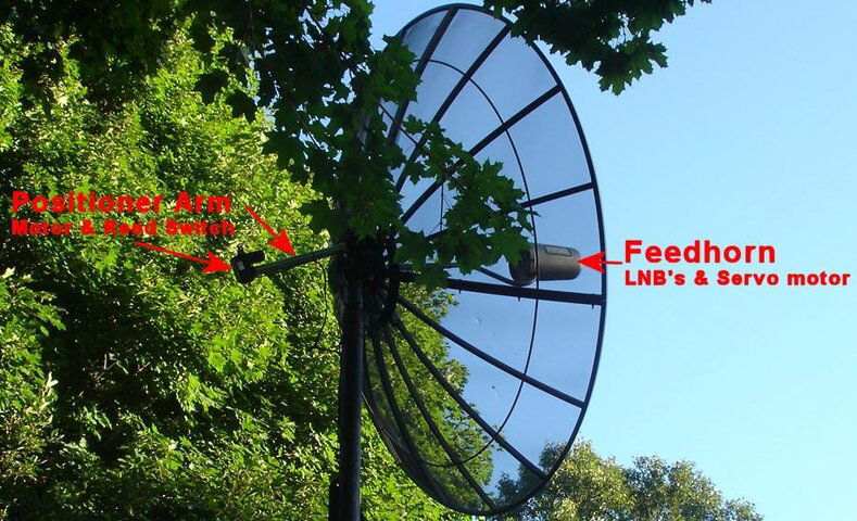
The motor wire connections would be underneath the plastic block or cover just above the Polarizer terminals. These are the ones marked M1 and M2. I assume the plastic cover can be unscrewed and then you attach the motor wires to the screws underneath. In the bundle of wires, there should be two wires that are not coax, but ARE obviously of heavier gauge than the other single wires. Those go to the M1 and M2 terminals. The motor is in the base of the positioner arm that sticks out behind the dish.
The bad part about this is that if you hook the wires up backwards, the dish will move west when the receiver says it's going east, and vise versa. Should that happen , reverse the two wires on M1 and M2. Unfortunately, you usually can't tell if you have it right until you try it.
There should be two other wires, perhaps smaller than all the rest - these go to the reed sensor switch (assuming that the positioner arm isn't older than Methuselah) and that would normally be the PULSE and GND screws on the terminal strip at the top. Again assuming that the arm is of somewhat recent vintage, the +5 screw is NOT used.
The motor wires and the reed sensor wires will often be in the same cable, but the two motor wires will be much larger than the reed sensor wires.
If they used a commercial satellite cable, there may also be a ground wire, usually it will be bare or in some way by itself. That would hook to the black binding post to the right of the Polarizer terminals, the one with the ground wire symbol underneath. If you don't see one don't worry about it; more than likely the receiver will work fine without it (although with a pole THAT high, I'd hope they took extra pains to keep all the grounds intact!).
So to recap, the three wires from the Polarizer (which is attached to the feedhorn) go to the bottom set of terminals, and should be in their own cable. The four wires from the positioner arm - the two heavy ones from the motor, and the two lighter ones from the reed sensor switch - should be in one or two other cables. The polarity of the wires coming from the reed sensor switch isn't important, but the polarity of the wires feeding the motor is - if you get them backwards the dish will move in the wrong direction, and you'll have to reverse them.
Having said all that, I've seen setups that don't go by these rules at all. For example, on my C-band dish, someone came up with a six wire stranded cable where all the wires were the same size (fairly heavy) to go to the positioner arm, so all I can do is watch the color codes at both ends (and lament that two perfectly good wires are unused). But that is a lot easier when the positioner arm is four feet off the ground! So I'm hoping that in your case, the standard ways of doing things are what you find.
C-band is where all the programming originates, just remember that-Make sure the dish tracks the arc, the motor is in good shape, and the pole aint lifting out of the ground. Channels are still there, but it isn't like the days of old when a dish picked up everything for FREE!
Thanks guys. The snow is falling today so my outside plans are on hold. Seems like a perfect time to start wiring my receiver up! I'll report back later tonight on how it went.
Stonedtone420 said:C-band is where all the programming originates, just remember that-Make sure the dish tracks the arc, the motor is in good shape, and the pole aint lifting out of the ground. Channels are still there, but it isn't like the days of old when a dish picked up everything for FREE!
Not quite all. NBC is Ku which is why they have HDTV problems every time it rains hard in New York.
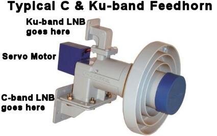
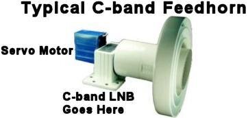
Okay, only AFTER I composed my response to this did I realize that this message is over two months old. So you have probably figured all this out, but in case any other newbies wander in here, the three illustrations here should give you an idea of where the various pieces go. If you want to see more pictures of feedhorns (including ones with LNB's attached, go to Google, click on Images, then search for either "Feedhorn" or "Corotor II" (the latter is a specific model of C & Ku feedhorn). Whether the dish is C-band only or C & Ku band depends mostly on which type of feedhorn you have, and which type of LNBs, and whether they are still in working condition.madpoet said:Stupid question of the day... I don't understand the difference between C-Band and Ku. I keep readin how people are using their dish for both. I always thought Ku was what fed the small dishes, but I guess I'm wrong. I found the following post:
"a fullview system now is made up by a 10' dish c/ku band feed and lnbs a 4dtv with hdd 200 and VCII+ board a DVB box slaved"
Now I'm really getting confused. I've got a dish, I have (I assume!) some sort of LNBs somewhere (not sure where they are located) and a 4dtv receiver. I already know I don't have the HDD200, I don't guess I have the VCII+ board since I can't figure out what it is or where it would be, and I'm not sure what a slaved DVB box would be either
. I'm starting to think I'm in way over my head!
Attachments
Last edited:
MP... what PJ are you going to hook it too? I have been eyeballing getting my BUDs back up and hooking to my X1...
Well, my dish isn't moving. Anywhere. Which frustrates me because I was told it worked when I bought it, but it obviously isn't. I'm having the guys who set it up come out and check it out, but with all the snow I'm not sure when that will be. Very disapointed.
dfergie, being the glutton for punishment that I am I went with a CRT projector this time around... 8500LC. And man, is that thing a royal PITA!
dfergie, being the glutton for punishment that I am I went with a CRT projector this time around... 8500LC. And man, is that thing a royal PITA!
I'm back  . My projector is mounted, so I'm tackling this again. The guys that installed it are coming out on Saturday to figure out what's up, so I'm hopeful to have it up and running this weekend. Still need the digital box to go with my 4dtx receiver.
Just for Giggles, check out the Fta/Dvb section and PSB's Review of the DVB world USB box... I just got one but have not got it going yet... 
- Status
- Please reply by conversation.
Similar threads
- Replies
- 3
- Views
- 681
- Replies
- 37
- Views
- 4K
- Replies
- 2
- Views
- 701
- Replies
- 8
- Views
- 524


