We'll use OHM's LAW:
E(voltage)= I(current) x R(resistance)
P(Power)= I(current) x E (voltage)
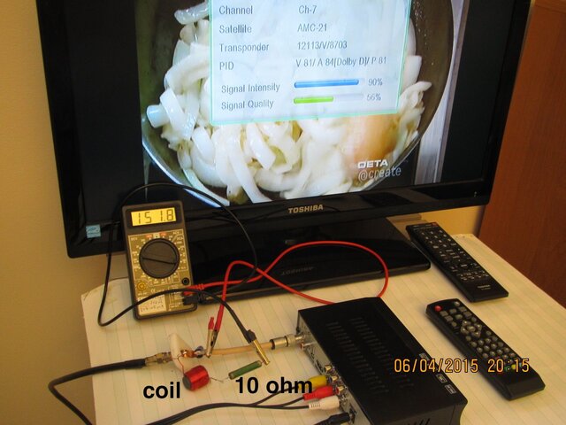
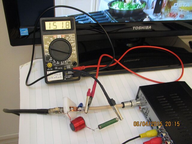
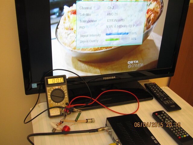
The best way to measure the voltage being supplied to the LNBF/LNB is with a load. As can be seen in the following, only supply voltage can be measured
with the load (LNBF) disconnected.
12v---^^^^1k^^^---(12v)----^^10Mohm^^--GND effectivly an Open circuit
12v ---^^^1k^^^---(6v)--^^1k^^^--GND A "Loaded" circuit
The voltmeter presents too high a resistance to effectivlely 'load' the circuit. The supply will see many megaohms as a load.
WHY?
Your LNBF normally draws 120ma (.12 amp) @ 18v.
It's resistance/impedance equivalent is 18/.12= 150 ohms
Say your coax has corrosion in a connector that represents 10 ohms.
With the 10 ohms in series with the 150 ohms of the LNBF the total circuit resistance is 160 ohms. With 18v supplied, and 160 ohms the circuit current is now only 18/160= .1125 amp (.1125ma).
The LNBF voltage is now what?
150 ohms X .1125 = 16.875 Volts.
That may not be high enough to switch your LNBF to horizontal polarity.
So how do we easily 'load' our LNBF system to test?
Parts Required:
Top:
1) 150 ohm - 5 watt power resistor
Bottom left to right
1) F-81 barrel connector
1) electrical 'ring connector'
1) F connector nut

Fasten the ring terminal onto the the F-81 with the nut:

Insert one lead of the resistor into the F-81. Other lead goes to the ring terminal.

Testing: Voltmeter positive lead to F-81 side of resistor, Negative lead to the 'ring' lead.

NOTE: one could use a lower value resistor.
100 ohm would draw 180ma (PLL LNBF equivalent?) in a 'good' system @ 18v.
Power rating of the resistor is determined by increasing the system voltage 10%: 18x1.1= 19.8 round to 20.
System current (@ design resistance 150 ohm) also increased by 10%
18/150=.12 x 1.1 = .132
E x I = P: 20 x .132 = 2.64watts A 5 watt rated resistor will stay relatively cool.
and standard values are 1 and 5, so 5 it is.
Happy troubleshooting!
E(voltage)= I(current) x R(resistance)
P(Power)= I(current) x E (voltage)
The best way to measure the voltage being supplied to the LNBF/LNB is with a load. As can be seen in the following, only supply voltage can be measured
with the load (LNBF) disconnected.
12v---^^^^1k^^^---(12v)----^^10Mohm^^--GND effectivly an Open circuit
12v ---^^^1k^^^---(6v)--^^1k^^^--GND A "Loaded" circuit
The voltmeter presents too high a resistance to effectivlely 'load' the circuit. The supply will see many megaohms as a load.
WHY?
Your LNBF normally draws 120ma (.12 amp) @ 18v.
It's resistance/impedance equivalent is 18/.12= 150 ohms
Say your coax has corrosion in a connector that represents 10 ohms.
With the 10 ohms in series with the 150 ohms of the LNBF the total circuit resistance is 160 ohms. With 18v supplied, and 160 ohms the circuit current is now only 18/160= .1125 amp (.1125ma).
The LNBF voltage is now what?
150 ohms X .1125 = 16.875 Volts.
That may not be high enough to switch your LNBF to horizontal polarity.
So how do we easily 'load' our LNBF system to test?
Parts Required:
Top:
1) 150 ohm - 5 watt power resistor
Bottom left to right
1) F-81 barrel connector
1) electrical 'ring connector'
1) F connector nut
Fasten the ring terminal onto the the F-81 with the nut:
Insert one lead of the resistor into the F-81. Other lead goes to the ring terminal.
Testing: Voltmeter positive lead to F-81 side of resistor, Negative lead to the 'ring' lead.
NOTE: one could use a lower value resistor.
100 ohm would draw 180ma (PLL LNBF equivalent?) in a 'good' system @ 18v.
Power rating of the resistor is determined by increasing the system voltage 10%: 18x1.1= 19.8 round to 20.
System current (@ design resistance 150 ohm) also increased by 10%
18/150=.12 x 1.1 = .132
E x I = P: 20 x .132 = 2.64watts A 5 watt rated resistor will stay relatively cool.
and standard values are 1 and 5, so 5 it is.
Happy troubleshooting!


