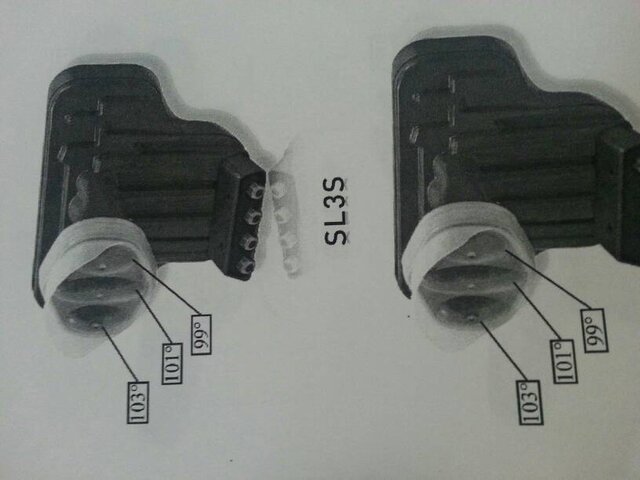
first time set-up
- Thread starter vixens
- Start date
- Latest activity Latest activity:
- Replies 281
- Views 41K
You are using an out of date browser. It may not display this or other websites correctly.
You should upgrade or use an alternative browser.
You should upgrade or use an alternative browser.
- Status
- Please reply by conversation.
So this conversation is going on in 2 separate threads ?
Personally, I think the guy is pulling your leg, probably has a SL3 set up elsewhere that you haven't seen.
Personally, I think the guy is pulling your leg, probably has a SL3 set up elsewhere that you haven't seen.
I saw the picture on tv and switched through the channels. there is no other sat dish on his property.
Later I sent a friend with a tele lens to take pics of his set up on his roof.
This is for real.
Later I sent a friend with a tele lens to take pics of his set up on his roof.
This is for real.
Just because you scrolled thru his channels, doesn't mean it's not on another dish.I saw the picture on tv and switched through the channels. there is no other sat dish on his property.
Later I sent a friend with a tele lens to take pics of his set up on his roof.
This is for real.
oh yes, they have put a fake 8 foot dish on to the roof, equip it with brand new triple lnbs and that's all just to bluff me.
Sure, good thought.
And if I would have $1000 to pay for his installation (or be willing to pay) I would not be in this forum. And if you apply this to all members here, that entire forum would not exist.
Sure, good thought.
And if I would have $1000 to pay for his installation (or be willing to pay) I would not be in this forum. And if you apply this to all members here, that entire forum would not exist.
Last edited:
Have you tried what I suggested in your meter thread?
Sent from my SPH-L710 using Tapatalk 2
Please refresh my mind.
Can we get these merged or one closed Plz this is getting confusing
Sent from my SPH-L710 using Tapatalk 2
Sent from my SPH-L710 using Tapatalk 2
I meant on the akhi dish not your 8footer. I'm running out of ideas to help with this. You said you know someone with this set up working. Maybe ask them if you can take some close up pics of the lnbs and specifically splitters or switches. Make sure they're close ups.
What I understand: it will need at least an 8 foot dish for the ka band satellites 99W and 103W. 101W would work with a 6 foot. The largest Alaska/Hawaii dish offered is just 4 foot.
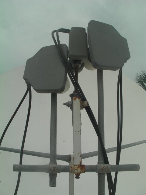
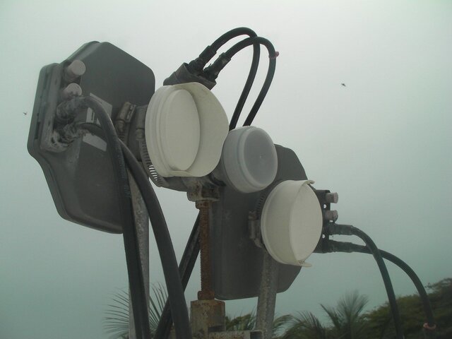
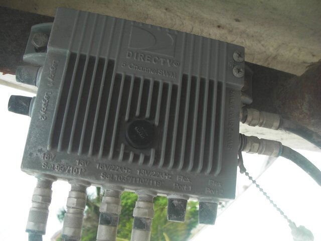
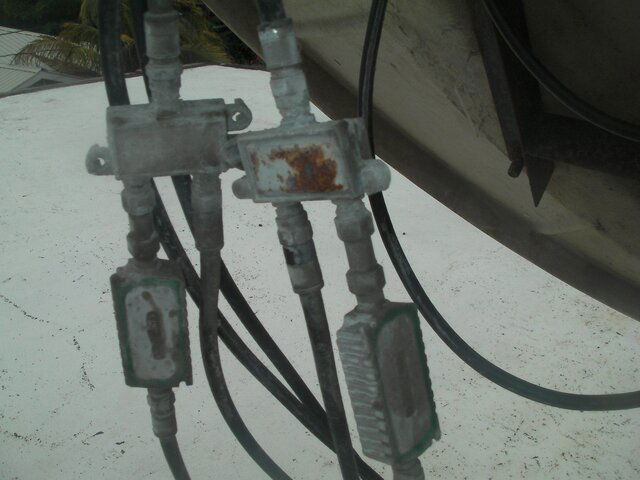
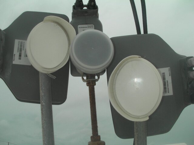
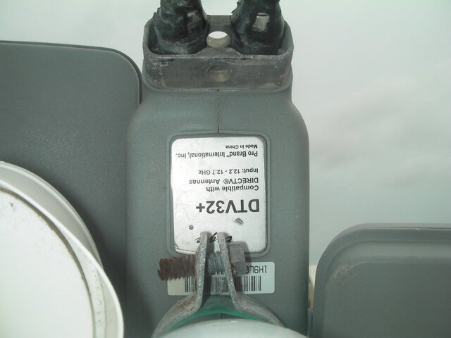
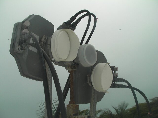
Here is what I observed and photographed:
Non SWM lnbs for Ka band. The right Ka lnb 103W (seen from behind the dish) is combined with the Ku 101W and the 101W has an inline amp before it is combined and hits the switch. The other Ku lnb 99W goes straight into the 99/101 inlets of the switch.
Every LNB uses two cables to the switch.
Two exits from the switch go to 2 receivers HR24 SWM. One receiver has the power amplifier which comes with the 6x8 SWM switch.
Let me know your thoughts. Thanks !
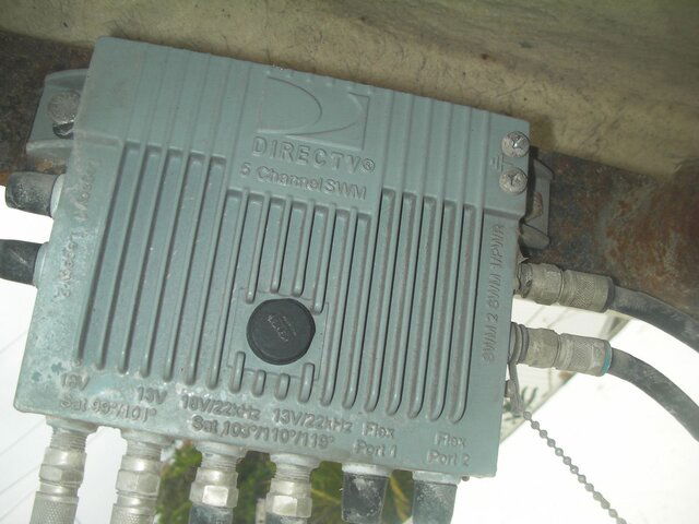
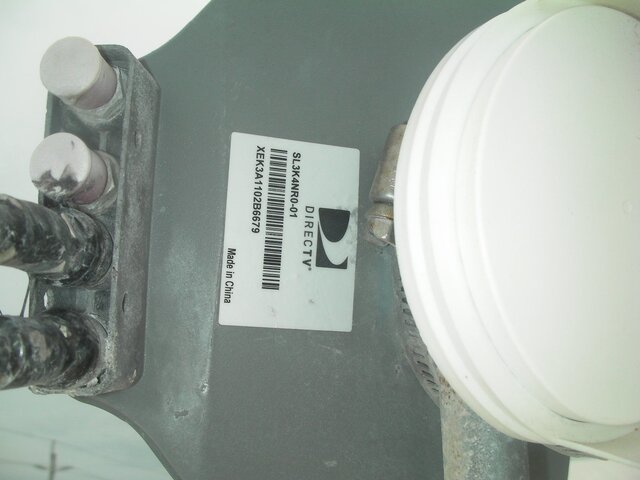
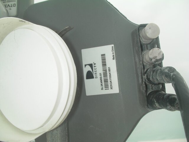
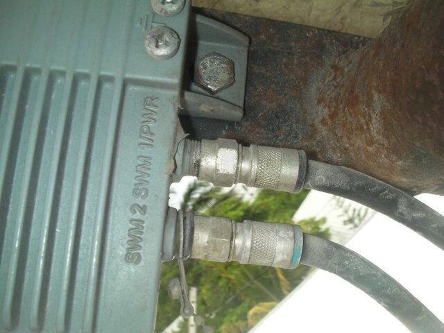
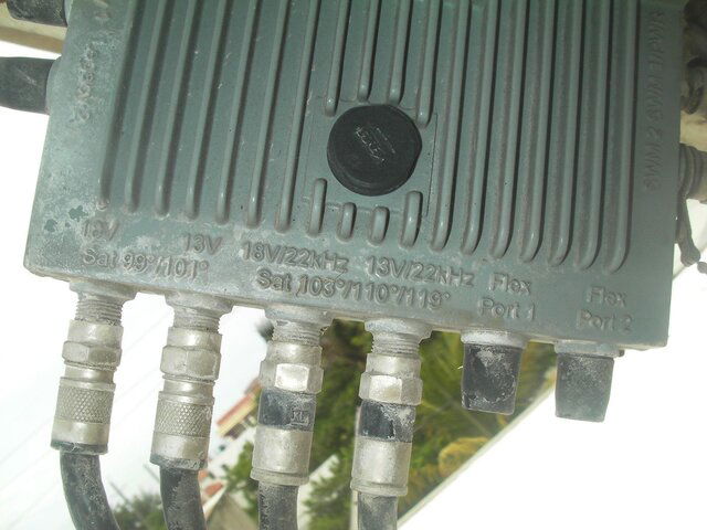
I will be using a HR22 (non SWM) with 6x8 Ka/Ku switch, non SWM.
Non SWM lnbs for Ka band. The right Ka lnb 103W (seen from behind the dish) is combined with the Ku 101W and the 101W has an inline amp before it is combined and hits the switch. The other Ku lnb 99W goes straight into the 99/101 inlets of the switch.
Every LNB uses two cables to the switch.
Two exits from the switch go to 2 receivers HR24 SWM. One receiver has the power amplifier which comes with the 6x8 SWM switch.
Let me know your thoughts. Thanks !


I will be using a HR22 (non SWM) with 6x8 Ka/Ku switch, non SWM.
Last edited:
Here is what I observed and photographed:
Non SWM lnbs for Ka band. The right Ka lnb 103W (seen from behind the dish) is combined with the Ku 101W and the 101W has an inline amp before it is combined and hits the switch. The other Ku lnb 99W goes straight into the 99/101 inlets of the switch.
Every LNB uses two cables to the switch.
Two exits from the switch go to 2 receivers HR24 SWM. One receiver has the power amplifier which comes with the 6x8 SWM switch.
Let me know your thoughts. Thanks !
View attachment 88138View attachment 88139View attachment 88140View attachment 88141View attachment 88142View attachment 88143View attachment 88144View attachment 88145View attachment 88146View attachment 88147View attachment 88148View attachment 88149
I will be using a HR22 (non SWM) with 6x8 Ka/Ku switch, non SWM.
Wow... not that I'm gonna call you a liar but I have some serious issues believing this would work properly. Without seeing the labels on the splitters and amps that are rusted out there's no way I can for sure copy its setup.
My theory is those are high amp diplexers combining the 101 and 103.
I have a theory... but it's not a solid one.. try to use 3 sl3 LNB's.. peak each one per satellite. Obtain two zinwell 4x4s and one 6x8. Run two inputs from the sl3 for the 99 along with two cables from the lnb for the 101 into one 4x4. I'll call this 4x4A. Next run two cables from the lnb for the 103 with the other two cables from the 101 into 4x4B. Then run two cables from 4x4A into the first two ports of the 6x8. Then another two cables from 4x4B into the second two ports of the 6x8. Run two lines from the outputs of the 6x8 to your dvr with bbcs attached.
No idea if this will work but I'm trying... hutch what ya think about this in theory...
Sent from my SPH-L710 using Tapatalk 2
In theory, yes. I think it would work. I'm still struggling and have been for days since I've been following this thread is how to Diplex/combine the 99 and 103 without losing every other transponder on one of those birds. Without seeing the splitters since they're all rusted up I can't tell for sure but I'm wondering, could you possibly use 2 power pass splitters? I've used them on 18 inch dishes just to try and they worked so I'm wondering if backing feeding the 2 signals in to the "out" slots on the power pass if this would possibly work as a way of combining the 2 birds from multiple dishes?
ok. thanks !
pictures:
1.) one pic 1: which Lnb is for what satellite ? left to right: 103W, 101W and 99W. right ?
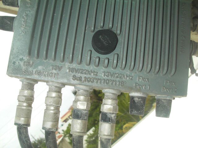
2.) on pic 2: The imputs are from left to right: 103W, 103W, 101+99W, 101+99W
My questions:
Why two cables per lnb to the switch?
Why does the 101W cables have the inline amplifier ?
Shouldn't the 101W be plugged into the 13V ?
For me with a HR22: wouldn't the non-SWM set-up be much easier ?


Last edited:
ok. thanks !
pictures:
1.) one pic 1: which Lnb is for what satellite ? left to right: 103W, 101W and 99W. right ?
2.) on pic 2: The imputs are from left to right: 103W, 103W, 101+99W, 101+99W
My questions:
Why two cables per lnb to the switch?
Why does the 101W cables have the inline amplifier ?
Shouldn't the 101W be plugged into the 13V ?
For me with a HR22: wouldn't the non-SWM set-up be much easier ?
View attachment 88159View attachment 88160
As for the amp om not sure... but I now believe these splitters are actually stacker s combining the 101 and 99. The 103 lines can be direct as you are not pulling the 110 or 119. Without trial and error no1 here can tell you for sure what is going to work. We're all taking educated guesses. Btw the correct order for sats is 99/101 and then 103 as you can read in the he pic of the switch.
I would believe the 6x8 will be less expensive than the Swm8 but neither are easier to install than the other in your case. Getting the dish aligned and lnbs to send the proper signals is gonna be your issue.
Sent from my SPH-L710 using Tapatalk 2
Yes, it's the 99 and 101 that have to be combined, and that combines two cables from each LNB, to give two cables, one for the even transponders (18v) and one for the odd transponders (13v). The 103 is two cables, even and odds.
Without some "surgery" to the LNBs themselves, I don't see how this is going to work. Then you need to calculate where the LNBs have to be positioned, to get the signals, and then get the LNBs/dish aligned.And even then I am not convinced. Someone who really understands satellite technology might be able to put something together but the OP just does not have the knowledge to do this, as far as I can tell.
Without some "surgery" to the LNBs themselves, I don't see how this is going to work. Then you need to calculate where the LNBs have to be positioned, to get the signals, and then get the LNBs/dish aligned.And even then I am not convinced. Someone who really understands satellite technology might be able to put something together but the OP just does not have the knowledge to do this, as far as I can tell.
Q: in the pic above
Which is the 103W lnb and the 103W lnb
wouldn't they be opposite to the actual satellites in the sky ?
If so, the 103W Lnb would be the left in the pic and the 99W Lnb would be to the right.
btw. thank you all for your educated info and guesses. Every little bit will help to get me started.
Which is the 103W lnb and the 103W lnb
wouldn't they be opposite to the actual satellites in the sky ?
If so, the 103W Lnb would be the left in the pic and the 99W Lnb would be to the right.
btw. thank you all for your educated info and guesses. Every little bit will help to get me started.
Last edited:
Q: in the pic above
Which is the 103W lnb and the 103W lnb
wouldn't they be opposite to the actual satellites in the sky ?
If so, the 103W Lnb would be the left in the pic and the 99W Lnb would be to the right.
btw. thank you all for your educated info and guesses. Every little bit will help to get me started.
If you are standing behind the reflector of the dish looking at the lnb facing you, from left to right the satellites are going to be 103 101 99.
BTW while unsure of the amplifiers on the 101 or their purpose I would use one of these http://www.solidsignal.com/pview.as...directv-approved-4x4-multiswitch-(sam4402-3a)
(I know it says discontinued, but it is available on ebay) to combine the 101 and 99 rather than whatever those two splitters are. then run two lines from the output of that 4x4 into the first two inputs of your 6x8, then two direct lines from the 103 lnb into the next ports, then obviously two lines from the 6x8 to the receiver, again dont forget the bbcs.
ok, I ordered a SAM-4402-3A DTV switch. Thanks !
I will start experimenting soon and keep you updated.
I will start with the Hawaii/Alaska triple lnb but I am pretty sure that it's too close together for a 8 foot dish.
I am wondering when the cover is removed if the three feedhorns could be spread.
Any other thoughts and suggestions are very welcome.
Thanks !
- Status
- Please reply by conversation.
Similar threads
- Locked
- Replies
- 4
- Views
- 1K
- Replies
- 24
- Views
- 2K
- Replies
- 3
- Views
- 1K
- Replies
- 2
- Views
- 1K


