Experimenting with L-Band antennas

Status
Please reply by conversation.

N6BY

Geek
Original poster
Lifetime Supporter
Mar 1, 2006
3,292
3,248
Roseville, CA 121W
I have built and modified some L-Band antennas over the past couple of weeks and thought it might be good to start a thread for sharing various L-Band antenna design projects and their performance.

Currently, L-Band is used for Outernet, Aviation, Maritime, FAX, paging, vessel tracking and miscellaneous other services. The frequency range is around 1.5 GHz for receiving and 1.6 GHz for transmitting. It uses RHCP (right hand circular polarity). But when an RHCP signal reflects off a surface it becomes LHCP.

Below are two of the antennas I made and my modified patch antenna:
HelicoilOnBirdview.jpg

3 Turn LHCP coil on Birdview

RHCPCoil8Turns.jpg

8 turn RHCP coil

PatchModified.jpg

Modified patch antenna showing LHCP feed added (left side of photo). Stock RHCP feed on right .

PatchOnBirdview.jpg

The patch at the Birdview's focal point and the coax connected to the LHCP feed point.


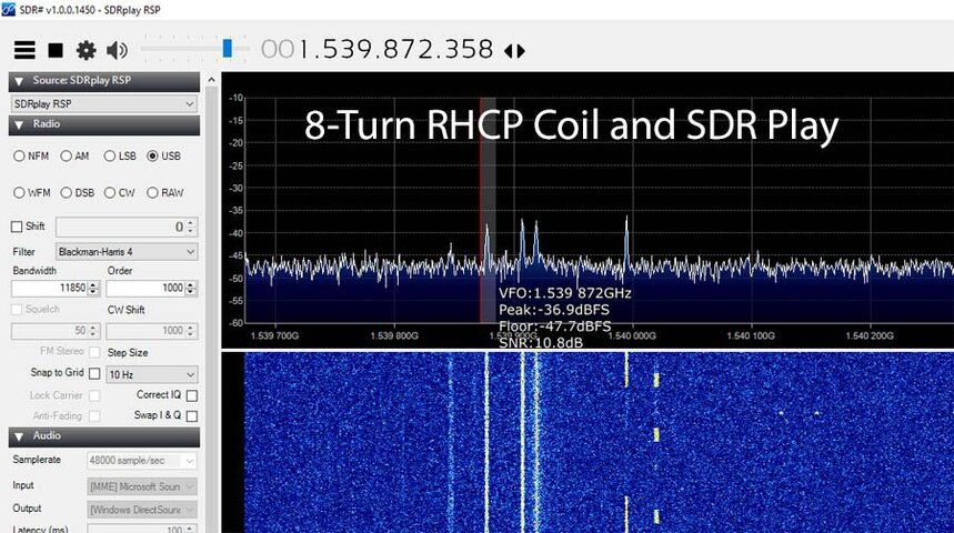
First I made an 8-turn RHCP helical coil. I used bare 14 gauge copper wire wound around a 2" ABS pipe with a round ground plane made out of sheet metal. I just used clear tape to hold the pipe in place and the wire on the tube. (If I had planned on using it long term I would have done it differently). I mounted an F-Connector on the sheet metal for easy connection to a coax cable. I got an SNR of 10.8 dB on the Outernet frequency using my SDRPlay.

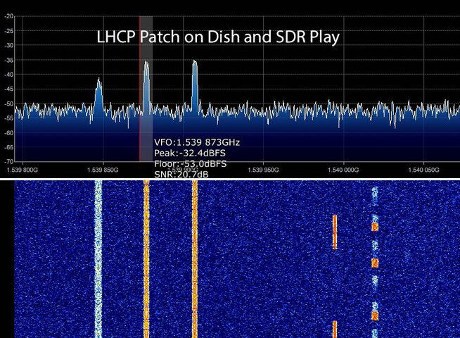
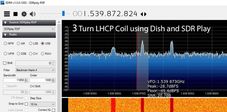
Next, I made a 3-turn LHCP helical coil for use with a satellite dish. I got an SNR of 20.7 dB for Outernet!

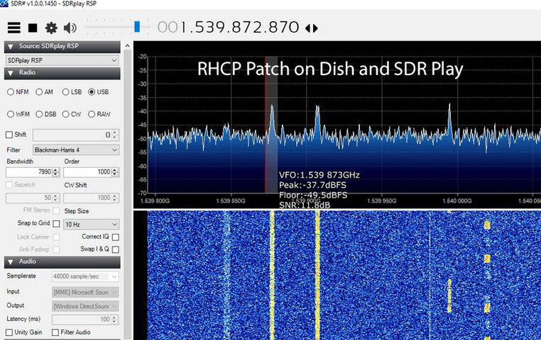
After that, I replaced the coil with an Outernet Air Gap Patch antenna that I purchased on Amazon. As purchased, it is RHCP and I figured there would be some loss since it was the wrong polarity for use with a dish. The SNR was 11.8 dB.

So then I modified the Patch antenna to receive LHCP by drilling a small hole and soldering a new pigtail on the other side of the corner -- see above photo. I kept the existing RHCP pigtail on because it wouldn't hurt performance. The SNR tuned to the Outernet frequency was 20.7 dB -- a gain of nearly 9 dB by changing the feed point for the correct polarity. It equalled the performance of the 3-turn LHCP helical coil on the dish.

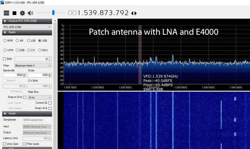
For comparison, I also tried the stock components sold by Outernet -- an E4000 SDR, LNA, and Patch antenna (before modification). Got a very low SNR of only 5.4 dB, which made the signal a bit difficult to spot in SDRSharp.

I don't have the Outernet CHIP computer so I did not actually try the Outernet Librarian software, but I am confident that if I did it would work very well with a 20.7 dB signal.

I have included SDRSharp screen captures showing the SNR's with the various configurations.

Next I plan to try the LHCP coil and patch antennas on a smaller offset satellite dish.
SNR_3TurnLHCP.jpg SNR_8TurnRHCP.jpg SNR_LHCPPatchDish.jpg SNR_PatchWithE4000.jpg SNR_RHCPPatchDish.jpg
 
Last edited:
Agreed the patch antenna would have gain aperture relative to the dish size at it's focal point, and easy to modify the antenna you have for polarity. Well done!

I have a 6' L-band parabolic with a linear feedhorn I have been thinking of modifying for this use. Just need to set up a mount and pole for it to track the arc, or maybe an az-el rotor. It's fairly light aluminum, built for a microwave backhaul for a local radio station to/from their transmitter/studio.
Only need some spare time!
I don't know how to calculate the 3 dB beam width of a patch antenna. But here is a link to a good calculator for gain and beam width for helical coils, based on the number of turns and wavelength: http://www.daycounter.com/Calculators/Helical-Antenna-Design-Calculator.phtml

For the 3 turn helical coil, the 3 dB beam width (the calculator calls it Half-Power Beam Width) is 60 degrees. My Birdview has an F/D ratio of 0.4 which equates to a 103 degree angle. So the coil is only 'seeing' a portion of the dish. The 3 turn coil has identical performance to to the patch when mounted at the focal point.

I will try changing the number of turns on the coil and placing it at different distances from the dish to see what works best. The other thing I need to do is adjust the coil so the feed point impedance is closer to 50 ohms. Its around 150 right now.

beamwidth.jpg
 
Thanks for the link to the Design Calculator. I've been looking for something like that.
I couldn't get the impedance to change by changing any of the Input parameters. Not sure it can be done.

There is another way to match the impedance to 50 ohms. From this document on page 4:

http://www.haystack.mit.edu/edu/undergrad/srt/pdf files/FinalReport.pdf

"The impedance matching method was changed from a tapered section at the end of the helix,
which gave a reflection coefficient of -13.2 dB, to a 1/8? by 1/16? copper foil plate
parallel with the helix, centered on the first quarter turn. This method reduced the
reflection coefficient to -23.5 dB."

This document has a photo of the design, Figure 8 on page 11:

http://www.haystack.mit.edu/edu/undergrad/srt/pdf files/SRT_Hardware_Manual.pdf
 
  • Like
Reactions: N6BY
Are you using this for Outernet only?
Are other things going to come out of this?
Will a mesh dish work?
What dish size is best?
Any limit on wattage?
What is data transmit limited to?
 
Are you using this for Outernet only?
Are other things going to come out of this?
Will a mesh dish work?
What dish size is best?
Any limit on wattage?
What is data transmit limited to?
No. Yes. Yes. Any size over 18". Don't know. Not using it for transmitting. :)

^^^ That was the short version....... Actually, I'm not downloading the files from Outernet (don't have the Linux setup for it). I'm just using it as a weak reference signal for testing various receive antennas.

There is much more on Inmarsat including the AERO channels where airports send various messages to airplanes about runway conditions, closures, airport hazards, equipment malfunctions, weather, etc. "JAERO" is a great program for reading the messages -- discussed here: http://www.rtl-sdr.com/jaero-a-new-rtl-sdr-compatible-decoder-for-inmarsat-aero-signals/

Also on each Inmarsat (except 97.6W) there is a channel dedicated to "STD-C EGC" which is where various agencies (mostly coast guard stations) broadcast informational messages to vessels. They warn them about navigation hazards, missing vessels and searches in progress, weather and other useful information for ships at sea. Ships are required to have the ability to receive these messages. Here is a link for more information: http://www.rtl-sdr.com/rtl-sdr-tutorial-decoding-inmarsat-std-c-egc-messages/

The above mentioned radio channels are not encrypted. There are other channels for private messages which probably are encrypted.

As for what I hope comes out of this -- better L-Band reception antennas, and maybe getting others interested in SDR (software radio), and sharing discoveries.

Regarding Outernet: from reading over at their discussion site I can see that the patch antenna + LNA + E4000 combo they are using is barely adequate at best, and not usable at all for some people. In my opinion, they either need to bump up the signal strength or provide a better antenna.
 
Dude that is pretty sweet!

Are you going to build something out so you can download?

What is your goal?
Highly fascinating
 
It has been quite interesting -- so much that I have all but stopped watching TV. I am enjoying SDR and antenna projects in my spare time.

I don't think it would be worth it right now to setup a Linux system for Outernet (for me at least). I am a bit disappointed that they have chosen to use a proprietary modulation scheme and the low level software for decoding the signal is not open source. Only the high-level "Librarian" part of it is open source. However, if Outernet decides to support other platforms like Mac and Windows then I would set it up here. Also they have plans to offer a two-way pay service for people who want remote internet. I would think that the 'receive only' service will always be free.
 
I just finished building a dual polarized 'septum' feed for receiving circular polarized L-Band. It's optimized for the NOAA's GOES-16 satellite to receive the GOES rebroadcast service (GRB) at 1686 MHz. The septum design has excellent cross-polarization isolation between RHCP and LHCP. The GOES-16 satellite transmits both RHCP and LHCP at the same time on the same frequency. So thats why it needs high isolation.

Tomorrow I will build a dish mount for it and test it.

If it works, I will use a similar design for Earth-Moon-Earth (EME) at 1296 MHz. EME communication has been on my bucket list for a long time!

A cross view diagram of the design and a photo looking down the feed are below.

septum_diagram.jpg

septum.jpg
 
Updated GRB septum measurements and construction details

Since the only square tubing I could find has an inside width / height of 4.5" (114 mm), I made some adjustments to the septum. The actual septum measurements are in the diagram below.

I ordered the square tube, septum plate, and back plate from onlinemetals.com A list of what I ordered is below. For a small fee they will cut their metal to the requested size, rounded to the nearest 1/4". When I received my order, I was pleased to see that the 4.5" x 11.5" plate fit perfectly inside the square tube. :)

I used a hand held circular saw with a Oshlun SBNF-070054 blade to cut the septum to the correct shape. After cutting I used a metal file to remove the burrs. The septum was mounted inside the square tube using MG Chemicals Silver Epoxy Adhesive, which is electrically conductive (and very expensive!).

The probes are made of 1/4" aluminum rod, which has a bevel I made by using a drill and file. Before beveling I drilled a small hole in the center of each rod for the copper wire, which was removed from some RG6 cable. After the beveling was done, I used "Aluminum Solder Wire 96.5 Sn/3.5 AG .062 Flux Core" to solder the copper wire into the holes I drilled in the aluminum rods.

For probe mounts I used female 'F' connectors. I drilled holes in the square tubing about 34.6 mm from the back which were slightly larger than the connectors. Drilling through the square tube was not easy! Its an extremely strong alloy, probably intended to be a structural support beam. Two nuts on each 'F' connector hold them in place.

Finally I inserted the probes into the 'F' connectors and taped the back plate onto the septum. So after all this, you may be asking why I used tape for the back plate? Because I wanted to be able to easily access the probes in case I needed to adjust them.

The final septum weighs in at 12.5 pounds! I wish I could have used a thinner / lighter square tube, but it was the only tube I could find.

Now, how to mount the big heavy thing to my dish struts? I made a 5 inch (inside dimension) square out of 2x4 wood. To get the mount to fit tightly I nailed the 2x4's together using the metal tube as a 'form'. Then I drilled holes in the corners of the wood square and bolted it to the struts using big wood screws. The septum slides into place, and the distance from the center of the dish is adjustable. My best results were obtained with the dish focal point slightly inside the mouth of the tube.

I built this last December. Initially I thought it didn't work very well. But recently I decided to give it another try. I attached a new Nooelec SawBird+ directly to the 'F' mounts using an 'F' to SMA adapter. Its powered using a home made bias tee / DC blocker that I made by gutting the insides of a TV splitter box. A 47 picofarad capacitor serves to block any DC from the DVB card on one side, and the other side has 5 volts from the computer's USB port to power the Sawbird+.

This septum performs very well for GRB. It's performance is on par or slightly better than the RF HamDesigns septum, and provides a strong enough signal to pickup GOES-EAST (75W) from California at 9.7 to 10.4 dB. (It varies).

I have no idea if this design is optimal. I may try variations on the probe length. Comments and questions are welcome!

GRB_Septum.png


Metal.jpg
 
Status
Please reply by conversation.

12V wall wart cluster

Users Who Are Viewing This Thread (Total: 0, Members: 0, Guests: 0)

Who Read This Thread (Total Members: 4)