Best Way to Receive Whole Ku Arc With Fixed Dishes?

Status
Please reply by conversation.
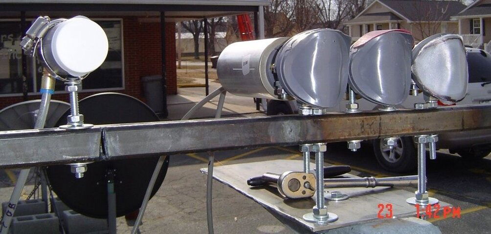
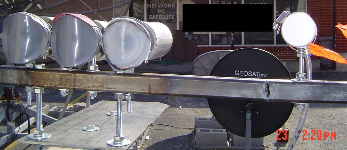
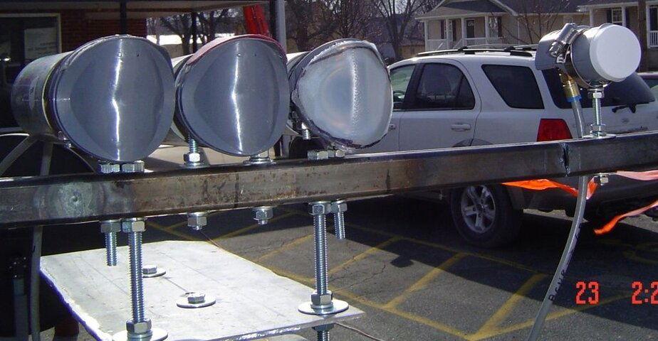
The 89° LNB looks like it's off by maybe 45 or so.
That's what I was thinking. It does have the H and V markings, but they are not consistent with the other two lnbfs.
It's certainly not out by 180°, which would be fine.
Are they all from the same era?
Do the outputs on each have the H and V marks?
No clue on history, and I wish it it was 180 out, then I could leave it alone. :)

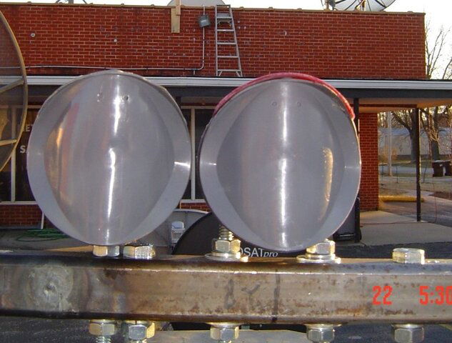
Cant tell how close the LNB -horns- are, since there's no picture from directly in front of them.
Think you might have room in that 48/52" to squeeze the camera in? :D
That's sure a request that couldn't be met on many little Ku dishes! - :up
See new picture below. :cool:

Don't give up on the Primestar LNBs.
I finally have one, so guess I can measure the horn width.
Assuming the horns on other LNBs like the JSC322 (or certainly the MINI dual) are smaller, you could use one of THOSE as the 91° LNB.
Then put a Primestar to each side at 89° and 93°
Next, two more small LNBs, and perhaps then another pair of Primestars.

I have discovered in the past two days that I only have 3 of these dual output can type Primestar LNBFs. The others I have are the dove bar shaped with huge horns and huge back ends which won't fit period, or the single output type which won't work for my purpose here either.

I'll try and slide the assembly out further and in further tomorrow to see what difference it makes. That is after I straighten out the problem with the 89 LNBF. :)

Pic below is after I took the 89 lnbf inside for inspection.

close-up-pstar-lnbfs.jpg

EDIT:
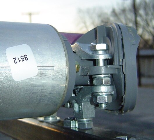
Forgot to add a picture of the center post bracket I made for holding Primestar LNBFs. It is made from an ordinary upside down ground clamp with the part that sticks up where you put the ground wire through drilled out and tapped for 1/4 inch bolts and the nut inside the upper part holds the LNBF holder, and the bottom half has the bolt threaded through and locked down with a nut on the bottom. :eek:

See the pic:

center-post-pstar-bracket.jpg
 
Last edited:
do the feedhorns that you have on the lnbs cause any loss ?
most of the primestar lnbf's were configured for Elliptical Dishes

maybe a feedhorn for the 1 meter primestar dishes would illuminate this big round dish better ?
 
I got outstanding signal on 91W with 12060V at a solid 99% SQ and nothing else lower than 90% SQ.

Flipped to the 89W LNBF and never got a signal. I have never used this particular LNBF, so I don't even know if it is working or not. Look at the picture of the three setting side by side and see if you notice anything. Someone may have gotten the can put on the horn incorrectly and have polarity out which might account for no signal. I'll swap it with the 93W position tomorrow and see if it does anything. :)

Jumped to the 93W LNBF, and got it without any problems. The signal was lower than I had anticipated it being so close to center. 75% SQ on Macy's. I will need to adjust a little.

Which receiver are you using (and what is the lower limit before pixelation)?

I agree that the 89 LNB looks off. Once did a similar thing with my old Star Choice LNB, took the "can" off and then proceeded to put it back on 90 degrees out (four screws hold it in place). Took a while to realise it, it was only after I did a blind scan and saw the results that I figured it out!
 
Linuxman, I recently found another use for that exact ground clamp... It's functioning as a speaker mount for Boston MicroMedia satellite speakers on a rolling equipment cart. Works like a charm... These ground clamps work well for a variety of uses :up
 
George wrote:
do the feedhorns that you have on the lnbs cause any loss ?
most of the primestar lnbf's were configured for Elliptical Dishes
I'm sure there is some loss, but the center lnb doesn't seem to show any.
maybe a feedhorn for the 1 meter primestar dishes would illuminate this big round dish better ?
I only have one of those, and I am going to leave it on the 1M. :)

Keith wrote:
Which receiver are you using (and what is the lower limit before pixelation)?
I am using my trusty Pansat 3500 to tune it in.

Depending on the channel, the threshold can be as low as 15 - 20% SQ.

I agree that the 89 LNB looks off. Once did a similar thing with my old Star Choice LNB, took the "can" off and then proceeded to put it back on 90 degrees out (four screws hold it in place). Took a while to realise it, it was only after I did a blind scan and saw the results that I figured it out!
That's what I think is wrong too. Someone at one time or another took it apart and put it back incorrectly. :)

Tron wrote:
Linuxman, I recently found another use for that exact ground clamp... It's functioning as a speaker mount for Boston MicroMedia satellite speakers on a rolling equipment cart. Works like a charm... These ground clamps work well for a variety of uses
Yes that particular clamp is easy to work with. Pretty soft metal to drill and tap which makes it suitable for a variety of purposes. :D

I am going to adjust the polarity on the 89W lnb and do some in and out experiments today.

More later. :eek:
 
Where to begin.

Started out by trying to set the polarity on the 89W lnbf, and discovered it was probably set correctly to start with. There was no covering on the horn when I got this lnbf off the dish it was on. I created the cover out of a milk carton.

After trying to switch polarities, still had no signal, so took horn back of and looked closely at the little plastic cover over the inner tube. It was pretty dirty and had a film on it. I cleaned it as best I could, and finally got some signal out of it, but only about half what I expected on 89W, so I think this LNBF may have a problem.

Slid the assembly away from the dish for testing focal length on the center three lnbfs. Got the length to 51 inches from the plastic cover on the 91W lnbf. I don't know exactly where you would measure the focal lentth because the horn is not round and the back part is about 51.5" focal length.

No change on 91W, still booming signals. No change on 93W. Macy's still at 75%, and spanish feed at 99% SQ. I checked the signal on my scanning dish for comparison SQ, my scanning dish gets those at 75% and 99% respectively, and my motorized Primestar 84e and FS IR-5400 gets them at 66% and 86% respectively, so I am pretty sure that is about as good as they are going to get. :)

I moved the assembly in to 49 inches on 91W, and no change on 91W. 89W, Macy's dropped to 60% SQ, but more on this later.

After moving the assembly back out to the 51 inches I had previously, I quick manufactured a holder for the bullet lnbf I have here as a spare. Stuck it in place for 101W, just to see if I could get anything. Just moved it around, back and forth, and up and down, and finally landed with signal. 3ABN was at 99% SQ, Apostolic Oneness was at about 60% SQ, but the old KUIL was at only 15% SQ.

I think with a little tweaking, and better holder, maybe a better arm with in/out to dish will make this distance out quite acceptable.

101W LNBF is 11 inches center to center from 91W and 52 inches from center of dish to front of LNBF. When I tried to move the LNBF further out, the signal got weaker. Couldn't get any further in, not enough movement in holder. The fact that it was only 11 inches from the center lnbf tells us the distance between lnbfs. Looks like an average of 1.9 inches per two degree spacing.

Moved the 101 lnbf to the 79W position, and began to look for signal. Finally found 11900 H and got it tuned in at about 45% SQ with a couple of feeds at about 15% SQ. Not quite enough for un-pixelateded watching.

The 79W lnbf is 11.5 inches from the center and 52.5 inches from the center of the dish to the front of the lnbf.

79W will require some work to make it acceptable. It is 12 degrees out from center and will need a better holder/adjustment and placement design.

I seem to get the best signal with all lnbfs pointed at the center, but have no way to tilt them which may be required.

I think Brian may be correct with his suggestion above of a rigid pipe of some kind that I can get bent easily.

I think it is also apparent that I may not be able to use the Primestar LNBFs even at the center.

My reasoning is that they are performing better at 51 inches because they are further apart, and at that focal distance being that far apart gives better signal.

I believe the real focal distance is going to be nearer the 48 inch length as the factory people told me it would be, and to get the best in the center and on the ends, I need to have smaller lnbfs at the center too. The center lnbfs are currently about 2-7/8 inches centers. From the distance out to 79 and 101, would indicate the distance for the centers to be more like 2-1/4 inch centers or closer.

I was in and out, mostly out for about 2 and half hours. The temp was in the mid 30's with 10-15 mph winds and gusts higher than that.

I couldn't take any more for the day, so I called it quits.

I won't have much good weather for at least another week. Will have to work on it when I can.

That will give me time to get a pipe, hopefully one I can bend myself. I have a hand pipe bender but will have to find out what size and strength it will bend. :)

I have some ideas for new brackets and holders, but want some ideas from you guys too. The brackets and holders need to be geared towards use with a pipe instead of a square tube.

As always, let me know what you think? :D

I appreciate any advice, comments, or ideas!

Here are today's pics:
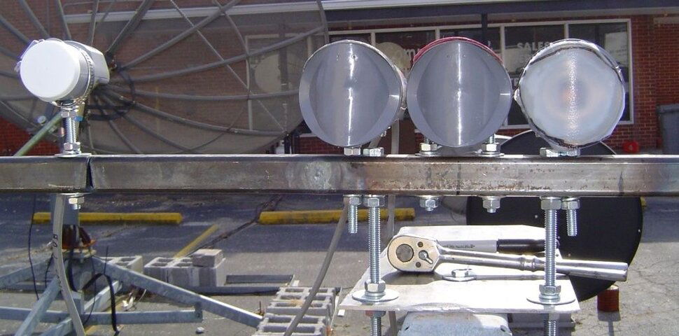
101-on-tube-test.jpg 101-on-tube-test2.jpg 79-on-tube-test.jpg 79-on-tube-test2.jpg
 
Well after doing some research on Prodelin's website I finally came up with a proper focal length sort of.

The line in bold below is the technical drawing I chose:

Antenna Size--- Band -- RX/O or RX/TX -Optics- Feed Horn OD--Degree--Tolerance Drawing #
*
1.8 meter-------Ku ------RX/TX---------- 0.6 ------5.23" -------51------- .25" -----TD0163


I have attached that document at the below.

I took off the square tube and support platform and put the monster lnbf back in place this morning to take some accurate measurements.

I know it is in the same place because the faded areas is still in the original platform.

The length I specified earlier was incorrect. It might be that I was measuring to the tube front or whatever, but what I have here now are the measurements.

Using the drawing below and their method of placing the feed-horn, they have:

A = 40.114 -- mine = 39.75
B = 44.107 -- mine = 43.75
C = 72.012 -- mine = 72.00
D = 69.31 -- mine = 69.25

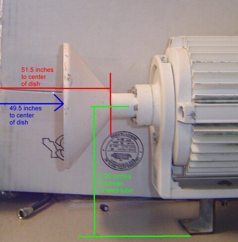
I have also included a picture with the focal lengths as measured by me this morning.

I am showing 49.5 inches to the mouth of the monster horn, and 51.5 inches to the mouth of the feed-tube. I think that was where I measured before but forgot where I took the measurement from. :eek: I am getting old and forgetful. :yikes:

From the table above, you can see the original feed-horn is 5.23" OD. My plan now is to use the Bullet LNBF from SatelliteAV all the way across the arc.

It's feed-horn measures 1.5 inches OD, about 1.25' ID and has about a 3/8" recess to the feed-tube.

On a prime-focus dish the Focal Length is measured from the center of the dish to 1/8" inside the feed-tube.

My questions are as follows:

1. How do I determine the focal length from the drawing and measurements below?

2. Where should I be measuring to, the mouth of the feed-horn, or the mouth of the feed-tube?


Forgive my ignorance on off-set dish measurements, but I feel it is important to get this nailed down accurately.

See drawing and pic below:

focal-length-exact-measurements-data.jpg

View attachment technical-drawint-td0163.pdf
 
If you want more control of your LNBF settings, switch from your present rectangular tube to 3/4 inch EMT conduit, which can be bent with a conventional pipe bender attached to a steel pipe. For examples of completed setups, look at pictures on the Global Communications website, specifically the multifeed ones on the 1.8 meter Prodelin that is pictured there. There is a huge difference in strength between the 1/2 and 3/4 inch diameter EMT electrical conduit, and since it is round, when LNBF adjusters are connected with conduit hangers, you have much more latitude in making otherwise odd mechanical adjustments.
 
My questions are as follows:

1. How do I determine the focal length from the drawing and measurements below?

2. Where should I be measuring to, the mouth of the feed-horn, or the mouth of the feed-tube?

By center of dish, I assume you mean the position of half the width and height. This is not the focal center for an offset dish (where the feed is pointed), which will be lower.

Using the measurements from the diagram and the 5.23" OD of the feedhorn mouth, I used the law of cosines to get the basic angles of the triangles. Knowing the vertical length of the dish would have saved a step, but I calculated it to be about 76.3", which seems within reason for a 1.8m offset dish. You should check that is actually the case.

From this the angle from dish top to bottom as seen from the center of the feedhorn calculates as 81 degrees. Using the law of tangents, I then calculated the length from the focal center of the dish to the feedhorn mouth as 40.1". This is the distance to the dish from the feedhorn center projected perpendicular to its mouth, and not the distance to the center of the dish. This calculation is only approximate.

I shouldn't hazard a guess as to where the focal point occurs inside the feedhorn mouth. That could be a bit dicier unless someone happens to know it off-hand for this particular type of feedhorn. Regardless, knowing the location of the focal center is the first step.
 
another way to skin the cat...

Maybe it would have been easier to shove a 99¢ laser pointer up the LNB.... :eek:
... and see where the dot fell on the face of the dish. - :rolleyes:
Might not be too late.
I think you said the LNB was full of water, and the 5" feedhorn face was damaged.

If I should obtain one of those dishes, that'll be the first thing I do. :cool:

edit:
Concerning where to focus in a given LNB...
If all LNBFs are identical, you focus one, and measure to the face.
Then, set the rest of 'em to match.
Probably should use an LNB with not so strong a signal, so maybe not the one in the center.
The lack of knowing does throw off the placement calculations a little, but if the error is on the order of ½" out of 50", that's only 1% and shouldn't matter.
 
Last edited:
If you want more control of your LNBF settings, switch from your present rectangular tube to 3/4 inch EMT conduit, which can be bent with a conventional pipe bender attached to a steel pipe. For examples of completed setups, look at pictures on the Global Communications website, specifically the multifeed ones on the 1.8 meter Prodelin that is pictured there. There is a huge difference in strength between the 1/2 and 3/4 inch diameter EMT electrical conduit, and since it is round, when LNBF adjusters are connected with conduit hangers, you have much more latitude in making otherwise odd mechanical adjustments.

Thanks Mike,

I bought a piece of 3/4" EMT conduit yesterday, and have been studying your pictures very carefully. I am in the process of getting a template made for the bends needed. :)

Pendragon wrote:
By center of dish, I assume you mean the position of half the width and height. This is not the focal center for an offset dish (where the feed is pointed), which will be lower.
There is a about a one inch circle with a dot in it that is the center of the dish.

Using the measurements from the diagram and the 5.23" OD of the feedhorn mouth, I used the law of cosines to get the basic angles of the triangles. Knowing the vertical length of the dish would have saved a step, but I calculated it to be about 76.3", which seems within reason for a 1.8m offset dish. You should check that is actually the case.
By my tape this morning I measured 76.25, so you are right on the money.

From this the angle from dish top to bottom as seen from the center of the feedhorn calculates as 81 degrees. Using the law of tangents, I then calculated the length from the focal center of the dish to the feedhorn mouth as 40.1". This is the distance to the dish from the feedhorn center projected perpendicular to its mouth, and not the distance to the center of the dish. This calculation is only approximate.
When laying the tape to get the vertical length, I looked at where the "center circle" fell on the tape and looking perpendicular to the face of the dish on the tape, the "circle" is at 39 inches from the top which puts the "circle" almost an inch lower than an exact distance of 38.125 inches as the halfway point on the tape.

I shouldn't hazard a guess as to where the focal point occurs inside the feedhorn mouth. That could be a bit dicier unless someone happens to know it off-hand for this particular type of feedhorn. Regardless, knowing the location of the focal center is the first step.
I agree!

Anole wrote:
Maybe it would have been easier to shove a 99¢ laser pointer up the LNB....
... and see where the dot fell on the face of the dish. -
Might not be too late.
I think you said the LNB was full of water, and the 5" feedhorn face was damaged.

If I should obtain one of those dishes, that'll be the first thing I do.
That is what I did yesterday when I re-assembled the big horn on the dish. My laser pointer puts the dot squarely on the "center circle" of the dish.

So I know where the original installer thought the center of the dish should be. :)

edit:
Concerning where to focus in a given LNB...
If all LNBFs are identical, you focus one, and measure to the face.
Then, set the rest of 'em to match.
Probably should use an LNB with not so strong a signal, so maybe not the one in the center.
The lack of knowing does throw off the placement calculations a little, but if the error is on the order of ½" out of 50", that's only 1% and shouldn't matter.
I agree and plan to implement that at the next opportunity. :D

I have the template for the bends drawn up only to discover that my little conduit bender is for 1/2". I am waiting now for a neighbor who is an electrician to return home from Church or wherever so I can borrow his. :eek:
 
When laying the tape to get the vertical length, I looked at where the "center circle" fell on the tape and looking perpendicular to the face of the dish on the tape, the "circle" is at 39 inches from the top which puts the "circle" almost an inch lower than an exact distance of 38.125 inches as the halfway point on the tape.

...

That is what I did yesterday when I re-assembled the big horn on the dish. My laser pointer puts the dot squarely on the "center circle" of the dish.

So I know where the original installer thought the center of the dish should be. :)

I'm basing my calculations solely on the diagram you attached, hoping the manufacturer knew the score. From this I calculate the focal center to be 47.9" from the top of the dish, or 28.5" from the bottom. This is a lot different from where the "center mark" is located, but is more in line where one would expect for an offset dish. If the LNBF is pointed at the calculated focal center, there will be about 40 degrees to the top of the dish and 40 degrees to the bottom. Using this point the calculated f/D is around 0.57.

If we take the "center mark" as the focal center, the LNBF would see about 33 degrees to the top of the dish and 47 degrees to the bottom. That means you would possibly miss some illumination on the bottom and be potentially looking at the sky on the top. Nevertheless, this would be a f/D of around 0.7.

Another way of looking at this might be measuring the dish offset angle. The "center mark" position would give 23 degrees vs. 17 degrees for the calculated focal center. The calculated focal center value seems low, but I haven't worked with one of these dishes. On the other hand the Prodelin diagram you selected shows an "Optics" value of 0.6. If that means f/D, it's pretty close to that of the calculated focal center (0.57). A direct measurement of the offset angle would resolve what the f/D of the dish actually is. I wouldn't want to miss aiming the LNBF by an amount these drastic discrepancies indicate.
 
Last edited:
I'm basing my calculations solely on the diagram you attached, hoping the manufacturer knew the score. From this I calculate the focal center to be 47.9" from the top of the dish, or 28.5" from the bottom. This is a lot different from where the "center mark" is located, but is more in line where one would expect for an offset dish. If the LNBF is pointed at the calculated focal center, there will be about 40 degrees to the top of the dish and 40 degrees to the bottom. Using this point the calculated f/D is around 0.57.

For what it is worth, this is what they sent me in the email I received from their tech support. The offset does not agree with the manuals, nor do I believe the focal distance to be correct.

43.2" Focal length
.6 F/D
Offset 22.6°

The manual says that it is 22.3 degrees offset, and I don't see how the 43.2 inch focal length could possibly be correct.

If we take the "center mark" as the focal center, the LNBF would see about 33 degrees to the top of the dish and 47 degrees to the bottom. That means you would possibly miss some illumination on the bottom and be potentially looking at the sky on the top. Nevertheless, this would be a f/D of around 0.7.

Another way of looking at this might be measuring the dish offset angle. The "center mark" position would give 23 degrees vs. 17 degrees for the calculated focal center. The calculated focal center value seems low, but I haven't worked with one of these dishes. On the other hand the Prodelin diagram you selected shows an "Optics" value of 0.6. If that means f/D, it's pretty close to that of the calculated focal center (0.57). A direct measurement of the offset angle would resolve what the f/D of the dish actually is. I wouldn't want to miss aiming the LNBF by an amount these drastic discrepancies indicate.

I just went out and measured the off-set angle where it is right now and pointed at 91W which for me should be about 44.9 elevation.

I took the measurements off the back support, and the dog leg at the bottom as illustrated in the manual using my digital level.

The one measurement show 67.3 degrees off vertical and the other shows 44.2 degrees taken off vertical with vertical being 90 degrees. I also measured with a 2x4 across the face of the dish and got 67.1 degrees.

That shows a current offset of 23.1 degrees and shows my elevation to be off by .7 degrees from where it is supposed to be.

See picture below which might account for the discrepancy in the center.

We are assuming the original installer knew what he was doing and assembled the dish correctly.

The manual states that the support arm should be assembled using at least an 18" square from the dog-leg on the back and the support arm on the front. The support arm is to be 90 degree perpendicular from the dog-leg on the back.

The manual also calls for an alignment tool to be place on the face of the big Horn. I don't have that alignment tool.

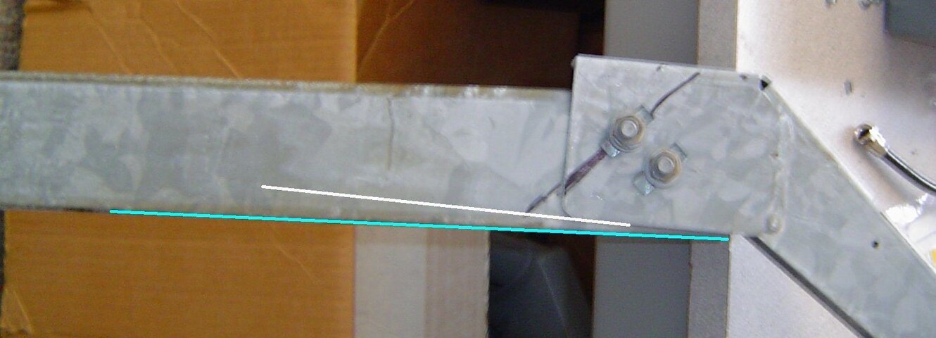
Note the discrepancy of the support arm platform and the arm itself in the picture.

The arm itself is 39 inches long. The discrepancy is 1/4" in the three inches of the adjuster surface. That could mean a huge discrepancy as to where the LNBF is supposed to be pointed. In 50 inches that would mean a lowering of a little over 4 inches below where it is now pointed at the "center circle".

One would think the support arm adjuster should be parallel with the support arm.

Note the picture:

support-arm-platform.jpg
 
From your measurements, the diagram doesn't match the specs sent by tech support and neither matches the way the original installer set up the dish.

I'm nervous about trusting the diagram because small errors in the A, B, C and D distances lead to significant shifts in pointing. Also the diagram values give a suspiciously low offset angle.

The discrepancy you pointed out in the picture seems significant. If the pointing is shifted 4" down, the focal length and offset angle shown in the specs start to look more reasonable.

If you want the correct values for the focal length and pointing angle, you could:

1. Make a number measurements of the dish depth along the major axis. This would have to be accurate enough to fit a curve and calculate the resulting focal position.

2. Measure the optimal LNBF position and orientation by varying the pointing angle and the focal length with the LNBF in place. Unfortunately this could require tweaking the dish for each trial position.
 
From your measurements, the diagram doesn't match the specs sent by tech support and neither matches the way the original installer set up the dish.
Agreed!

I'm nervous about trusting the diagram because small errors in the A, B, C and D distances lead to significant shifts in pointing. Also the diagram values give a suspiciously low offset angle.
Agreed!

The discrepancy you pointed out in the picture seems significant. If the pointing is shifted 4" down, the focal length and offset angle shown in the specs start to look more reasonable.
More reasonable, but I don't think they are accurate either.

If you want the correct values for the focal length and pointing angle, you could:

1. Make a number measurements of the dish depth along the major axis. This would have to be accurate enough to fit a curve and calculate the resulting focal position.
I will try and do that in the course of the next few days. It snowed here off and on through the day, and more is expected over the course of the next two days. I don't see anything in the forecast that will allow me to be out there for any length of time until Friday or Saturday.

2. Measure the optimal LNBF position and orientation by varying the pointing angle and the focal length with the LNBF in place. Unfortunately this could require tweaking the dish for each trial position.

That won't be a problem either once I get everything put back together at the next reasonbly "warm" day. I'll post the depths along the major vertical axis as soon as I can get them taken.

On another note, I did get the tube bent today, so will begin re-construction of platform and tube tomorrow. The tube in the picture is supposed to conform to the line below it. :)

See Pic below:

round-conduit-support.jpg
 
After looking at and downloading Mike Kohl's pictures (and blowing them up) of his Prodelins found here on his website, he could make life a lot easier on me by just going out and measuring the distance from the face of his center LNBF to the dish and take a laser pointer along so he can tell me where to point to on the face of the dish. :)
 
Pendragon wrote:
If you want the correct values for the focal length and pointing angle, you could:

1. Make a number measurements of the dish depth along the major axis. This would have to be accurate enough to fit a curve and calculate the resulting focal position.
I managed to get out there and put a string on the vertical axis of the dish today and lay down a tape measure along side of the string to take some measurements every 6 inches from top to bottom.

Here are the numbers starting at the top which is zero inches:

0" = 0.0"
6" = 1.5"
12" = 3.0"
18" = 4.25"
24" = 5.375"
30" = 6.0"
36" = 6.5"
42" = 6.5"
48" = 6.25"
54" = 5.75"
60" = 4.75"
66" = 3.25"
72" = 1.5"
76.25" = 0.0"

Hope these are close enough together and accurate enough to get a curve as required above.
 
Pendragon wrote:

I managed to get out there and put a string on the vertical axis of the dish today and lay down a tape measure along side of the string to take some measurements every 6 inches from top to bottom.

Here are the numbers starting at the top which is zero inches:

...

Hope these are close enough together and accurate enough to get a curve as required above.

The data you listed seem to be good enough for this purpose. After fitting the data I came up with the results that hopefully resolve your questions and may even tie some of the weird numbers that the manufacturer provided.

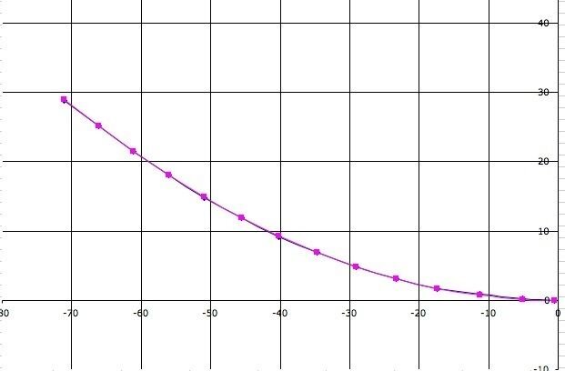
The fitted data are shown on the attached plot. The top of the dish is on the left, and the bottom on the right. This shows the parabolic section taken out of what would have been a prime focus dish. The blue line describes the measured data and the magenta line is for the fitted data. The agreement looks pretty good. The fitted offset angle is 22.3 degrees, very close to the apparent spec of 22.6. Once the parabolic section is rotated as on the plot, the true focal distance is 43.55". Note that the bottom of the dish would be nearly at the center of a prime focus dish.

So where should the feed be pointed? The angle subtended by the dish at the focal point is about 78 degrees. If we point the feed at the center of this angle, the focal point will be 49.19" from the dish. If you attach a string between the top and bottom of the dish, this center line will intersect 47.67" from the top of the dish and 28.61" from the bottom. The focal point should be 72.56" from the dish top and 43.56" from the dish bottom. These are not the distances to the feedhorn edges as shown on the diagram, but they appear to be fairly consistent.

I hope this resolves the uncertainties. It does look like the specs are in fact in good agreement, they were simply stated in an ambiguous fashion.
 

Attachments

  • CurveFit.jpg
    CurveFit.jpg
    17.9 KB · Views: 190
Last edited:
The data you listed seem to be good enough for this purpose. After fitting the data I came up with the results that hopefully resolve your questions and may even tie some of the weird numbers that the manufacturer provided.

The fitted data are shown on the attached plot. The top of the dish is on the left, and the bottom on the right. This shows the parabolic section taken out of what would have been a prime focus dish. The blue line describes the measured data and the magenta line is for the fitted data. The agreement looks pretty good. The fitted offset angle is 22.3 degrees, very close to the apparent spec of 22.6. Once the parabolic section is rotated as on the plot, the true focal distance is 43.55". Note that the bottom of the dish would be nearly at the center of a prime focus dish.

So where should the feed be pointed? The angle subtended by the dish at the focal point is about 78 degrees. If we point the feed at the center of this angle, the focal point will be 53.53" from the dish. If you attach a string between the top and bottom of the dish, this center line will intersect 38" from the top of the dish and 38.29" from the bottom. The focal point should be 72.56" from the dish top and 43.56" from the dish bottom. These are not the distances to the feedhorn edges as shown on the diagram, but they appear to be fairly consistent.

I hope this resolves the uncertainties. It does look like the specs are in fact in good agreement, they were simply stated in an ambiguous fashion.

Thank you very much for your time and efforts.

As soon as it quits snowing and warms up a little, I'll try and start putting some of this knowledge to good use. :)

Forecast looks like I might get a break on Saturday hopefully and they aren't wrong this far out. :eek:
 
Pendragon wrote:
So where should the feed be pointed? The angle subtended by the dish at the focal point is about 78 degrees. If we point the feed at the center of this angle, the focal point will be 53.53" from the dish. If you attach a string between the top and bottom of the dish, this center line will intersect 38" from the top of the dish and 38.29" from the bottom. The focal point should be 72.56" from the dish top and 43.56" from the dish bottom. These are not the distances to the feedhorn edges as shown on the diagram, but they appear to be fairly consistent.

After re-reading above, I am still a little confused about exactly where to point the lnbf on the dish surface.

I understand the string from the top of the dish and the bottom of the dish, top being 72.57" long and from the bottom being 43.56" long when drawn away from the dish.

I am still not sure exactly where to point it.

Would you mind using your graph above to draw a line where to point the LNBF?

Thanks again for your trouble!!
 
Status
Please reply by conversation.

Users Who Are Viewing This Thread (Total: 0, Members: 0, Guests: 0)

Who Read This Thread (Total Members: 5)

Top