Switching question (stumped so far)

Status
Please reply by conversation.

ayelvington

SatelliteGuys Family
Original poster
Jul 19, 2011
70
16
Russell, PA
Yes, I read the FAQ, but I regret that I don't see a common solution for this configuration:

MiniHD receiver
C-band BUD: Motor driven by V-box II, single-cable LNBF (Frequency stacked I'm told)
Ku dish: SG H-H motor (USALS), Universal LNBF

I was using a Diseq switch for a while and it worked nicely. However, the switch wasn't happy carrying the motor load, so I lost Ku.

Tried a 22 kHz switch, but that didn't work on Ku with the Universal LNBF

Is the solution to go to a standard LNBF, or is there a middle ground?

A
 
Wire as : Receiver--V-box-- Ku motor-- switch-- LNBF's
Use a diseqc switch if you use 22Khz for a universal Ku LNBF.

If I read this right, you recommend that I drive the H-H motor from the coax output of the V-box? Typ-art doesn't do the LNBF connections justice. Can you elaborate?
 
Yup. Receiver--v-box--then motor, then switch and lnbf's. V-box will handle motor/switch/LNBF load. it doesn't have switches, just listens for diseqc commands, so no problem passing the required current.
Typ-art doesn't do the LNBF connections justice. Can you elaborate?
I am brain dead trying to understand this.
 
Yup. Receiver--v-box--then motor, then switch and lnbf's. V-box will handle motor/switch/LNBF load. it doesn't have switches, just listens for diseqc commands, so no problem passing the required current.
I am brain dead trying to understand this.
That configuration doesn't resolve the root problem, that is that the Ku dish H-H motor draws too much current for a Diseq switch.

The more that I look at it, the more that the simple solution is to use a standard LNBF on the Ku dish (No conflict with 22kHz switch)

Thanks!
 
The motor current will not go through the switch IF the switch is between the motor and LNBF's. The motor current will only flow through the V-box. (AND that's OK)
Motor current, generated by the receiver, flows to the vbox then continues to the motor. Only LNBF and switch current flows from the motor to the switch, then off to the LNBF's
 
I am brain dead trying to understand this.
He means instead of a drawing you are trying to do ART/Draw with typing. It took me a couple of reads to figure that out too.
Receiver--->V-Box--> etc is what I think he means by [drawing] with text or type-art.

Anyway if you follow that ayelvington you will not have any motor current draw through the switch.
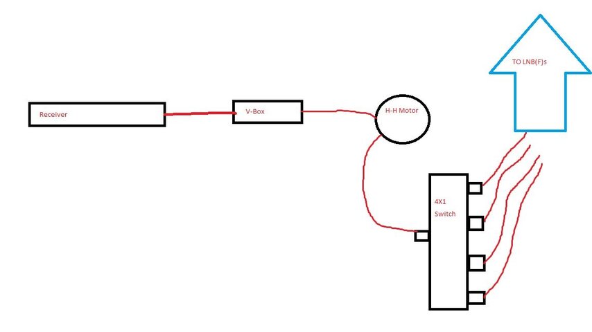
Just go from your receiver to vbox. Then out to HH motor. Then on the output of motor to the switch.

Here is a very quick and crude drawing. Red is your coax.

Crude Draw.jpg
 
  • Like
Reactions: FaT Air
With no 'typ-art'

First coax - Receiver LNB connection to the VBox
Second Coax - VBox to Ku motor receiver connector.
== == ( That's as far as motor current will flow )== ==
== ( from here on only switch and LNBF current )== ==
Third coax - Ku motor (LNB connector) to the switch (Receiver connector)
4th and 5th coaxes - Switch LNB connectors to the LNBF's
 
  • Like
Reactions: KE4EST
The replacement Ku LNBF arrives Wednesday; a 22 kHz switch should work fine then.

That said, the Ku LNBF is the termination for the H-H motor line. It's really not practical to pull another coax to be dedicated exclusively to the H-H motor.

The C-band dish is on the opposite end of the building along with the V-box. The wiring is tidy right now, and I hope to keep it that way.

Temps are down to 0F, so I'm going to lay low tonight, feed wood into the boiler, and be content with the satellite that each dish is aimed at (PBS and NHK)

Thanks to all,

Al
 
Ok, now can 'see', your predicament. C and Ku in opposite directions.
Good luck with the 22Khz switch. If that doesn't 'stand up' to the current and also fails, Here's one that will. Uses a mechanical 2 amp relay. ( scroll down the page to it )
2A Two Port Diseqc 1.0 Switch w/ Latching Relay
Although the previous posts is the 'norm' for most instances.
 
Last edited:
Ok, now can 'see', your predicament. C and Ku in opposite directions.
Good luck with the 22Khz switch. If that doesn't 'stand up' to the current and also fails, Here's one that will. Uses a mechanical 2 amp relay. ( scroll down the page to it )
2A Two Port Diseqc 1.0 Switch w/ Latching Relay
Although the previous posts is the 'norm' for most instances.

I want to make that switch just to say i did it.. Very cool. :rollingeyes
 
Good luck with the 22Khz switch. If that doesn't 'stand up' to the current and also fails, Here's one that will. Uses a mechanical 2 amp relay. ( scroll down the page to it )
2A Two Port Diseqc 1.0 Switch w/ Latching Relay

Well, if ayelvington can build that, he could also build an easy transistor power-bypass for a diseqc switch, I guess.
I have no experience with it myself, but I guess you only need a transistor, a resistor, a coil and a capacitor, and two 'splitters' of course to tap and to add the bypass; like in the drawing I made.

If he could open the switch and solder on the switch board itself, I guess only a transistor and resistor are needed, after cutting through the original power-path. Extra coil and capacitor are not needed then.

greetz,
A33

Edit: the drawing isn't shown flawlessly, I notice, though the original at my computer was OK. But the overall idea is clear....
 

Attachments

  • A33 diseqc switch power bypass.doc
    12.5 KB · Views: 284
Status
Please reply by conversation.

Sat Talk ?

New here but not to FTA, need help with SES3

Users Who Are Viewing This Thread (Total: 0, Members: 0, Guests: 0)

Who Read This Thread (Total Members: 1)