How to add a DiSEqC switch to a motorized system?

Status
Please reply by conversation.

PopcornNMore

SatelliteGuys Pro
Original poster
Mar 20, 2005
3,635
128
Gibsonia, PA
I have the following dishes that I would like to add to one receiver:

1) Motorized KU (SG2100)
2) Stationary KU
3) Stationary C

Tonight I used a 4 port DiSEqC switch by doing the following:
1) Motorized KU LNB to SG2100 to Input 1 DiSEqC.
2) Stationary KU LNB to input 2 DiSEqC.
3) Stationary C LNB to input 3 DiSEqC.
4) Output of DiSEqC to Coolsat 4000 receiver.

After setting up satellites within the Coolsat 4000 menu's it worked, but the motorized dish would not move.

Thinking that power wasn't being passed thru the DiSEqC switch I changed the coax cables on the motorized dish as follows:

1) Motorized LNB to input 1 of DiSEqC switch. Kept stationary KU on input 2 and stationary C on input 3.
2) Then took output of DiSEqC switch into LNB input of SG2100 H-H motor drive. Output of SG2100 was then connected to receiver.

This worked, but I don't like how KU dish moves whenever I want to switch to the stationary KU or stationary C dish. The motorized KU dish also often got confussed and wouldn't stop on a selected satellite. Instead it would keep on moving until I quickly selected another satellite. My satellites are configured using DiSEqC instead of URALS, so this may be interfering.

What would be the proper way to hook up all three dishes to one receiver if one is motorized?
 
I got a little confused about what you tried, with my setup I have the receiver connected to the motor and the motor connected to the switch, which is connected to all of my LNBs.
 
I got confused too just by writing it. :)

I too connected the DiSEqC switch to the motor in my second example above. However, when switching to either stationary system the motorized dish will move. I wanted to avoid this.
 
I believe on the Coolsat 4000 if you set the positioner to none the satellite name does not display on the satellite list for selection. However, I will try.
 
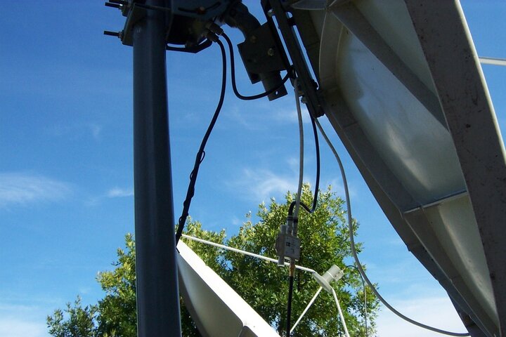
Picture Attached

Sometimes a picture is worth a thousand words. :)

I selected no motor control for the stationary LNB's and it works very well.

So, I learned that a DiSEqC switch does not pass power. This is why it failed when hooked up after the SG2100 motor drive.

In the attached picture you will see the LNB from the motorized dish (white coax) attached to the #1 input on the DiSEqC switch. The C band LNB from the stationary dish is attached to #2 input on the DiSEqC switch. The output of the DiSEqC switch is then attached to the LNB port on the SG2100. The receiver port on the SG2100 is then attached to the receiver.

Questions:
1) Do all DiSEqC switches not pass power?
2) The swich is labeled DiSEqC 2.0 and the receiver settings has DiSEqC 1.0. What are the differences in versions and does the Coolsat 600 support DiSEqC 2.0?
 

Attachments

  • SatelliteDish 026.jpg
    SatelliteDish 026.jpg
    251.6 KB · Views: 324
Last edited:
Sometimes a picture is worth a thousand words. :)
so where is the picture :)

Questions:
1) Do all DiSEqC switches not pass power?
correct
2) The swich is labeled DiSEqC 2.0 and the receiver settings has DiSEqC 1.0. What are the differences in versions and does the Coolsat 600 support DiSEqC 2.0?

I really don't know about the Diseqc 2.0 but most recievers control Diseqc 1.0
Diseqc 1.1 is uncommitted/committed switches (8x1 and above)
 
Thank you Iceberg once again. Does anyone know the loss of signal by using a DiSEqC switch?

I've noticed a slight loss. This is not a problem with KU, but it sometimes means a locked picture or not with using a 6' C band dish.
 
most Diseqc switches are 3db loss but in some cases I am running a LNB through a multiswitch, Diseqc switch and 22k switch and saw minimal loss versus a straight shot. My C-Band I lose about 2-3 points and that is through the above.
 
What would be the proper way to hook up all three dishes to one receiver if one is motorized?

I do exactly this and I have had voltage/current issues, but I solved them this way:

Put a regular 3 GHz NON-DiSEqC and power-passing splitter on the cable BEFORE the DiSEqC switch.
One single cable from the splitter goes to the motor ONLY.
NOTHING goes out of the motor. Just put a terminator on the motor's output jack. Remember, this cable ONLY drives the motor.
The other output of the splitter goes to the switch and the rest of the system including the LNBF on the motorized dish.
Yes! You will have two cables going to your motorized dish--one for the motor and the other for the LNBF.


Did I mention that the motor has nothing on its output jack? Good.

This simple solution solved my "motor moves too slow" or "motor is not moving east" problems.
The full power of the motor control and the USALS (or DiSEqC) commands go to the motor *almost* completely unimpeded.

I forgot to mention, too, that the motor will introduce an additional 4db-6db signal attenuation, while the splitter will be less than 2db depending on how much money you spent on it. Splitting the motor control at this first splitter avoids both voltage/current attenuation AND signal attenuation (especially if your DiSEqC switch won't pass the power needed to drive your motor).
 
Drawing

I drew a quick sketch of how the DiSEqC switch and high frequency splitter should be installed. Is this correct?

I assume the LNB port on the SG2100 motor drive is NOT used and is terminated and the REC port on the DiSEqC switch gets attached to the non-powered port on the high frequency splitter.
 

Attachments

  • Diseqc Setup.doc
    26.5 KB · Views: 283
.... the motor will introduce an additional 4db-6db signal attenuation, while the splitter will be less than 2db depending ....
This caught my eye, and has me wondering.. Is there an easy (and accurate) way to measure how much signal attenuation occurs when going through a device?

I'm rewiring and eliminating two barrel connectors and putting in new quadshield RG6 with compression fittings (instead of crimped), but had not thought about how my signal may be getting degraded simply because of the motors inline. I currently have an SG2100 moving via GOTOxx commands, with it connecting the lnbf side to a diseq, 1 port of a diseqc going to a VBOXII that is moving using Diseqc 1.0 commands, and then into a 22k switch splitting between C/KU on that leg of the diseqc. I plan on removing the barrel connectors and using new RG6+compression fittings, and bypassing the 22k switch since I only use the C-Band side anyhow. I'm wondering if I am actually losing more signal strength going through both motors than I would if I dropped in a couple hifreq splitters.
 
The easiest way (A spectrum analyzer would be the most accurate) is to directly connect your receiver to the LNB and compare the quality reading after you add a switch or other item.

With a Pansat (I only have access to this receiver) the signal quality scale is logarithmic.
 
This caught my eye, and has me wondering.. Is there an easy (and accurate) way to measure how much signal attenuation occurs when going through a device?

It is all estimation.
Before worrying about it, though, it only mattered on the FSS LNBFs, and inline amplifiers will *always* overcome lossage at a splitter or switch. HOWEVER, and this is a big HOWEVER, the current used by the inline amplifier will make the motor move more slowly--in extreme cases get another receiver to drive the motor all by itself if you don't mind it taking ages to move back to the east.

In my pile of junk most of the splitters have "3db loss" printed on them printed on each jack.
The DiSEqC switches have them listed in the specifications. Mine vary all across the board but they range from 2db (doubtful) to 6db.

The motor probably has frighteningly high loss on it, especially if it's a more modern motor that has a built-in DiSEqC switch in it (and they are only 2-output switches at that which won't work in your application).
 
I drew a quick sketch of how the DiSEqC switch and high frequency splitter should be installed. Is this correct?

I assume the LNB port on the SG2100 motor drive is NOT used and is terminated and the REC port on the DiSEqC switch gets attached to the non-powered port on the high frequency splitter.

That is correct, except the splitter will have to pass power to both outputs--the LNBFs and switches need power, too. Since you'll be connecting in parallel you will get stronger current to run the whole thing (the other way it would have been in series). Not all that much more current, but enough to run the whole thing within requirements which, before, it probably wasn't. I also have a 20db inline amplifier connected to the FSS Ku-band LNBF and I have verified that it is not only getting enough currrent but also it is indeed increasing the signal strength.

One thing about those terminators--I have come across some cheaply made ones that shorted. I don't think it will happen to you but be sure the terminator on your motor doesn't get warm like mine did.
 
Thank you Iceberg once again. Does anyone know the loss of signal by using a DiSEqC switch?

I've noticed a slight loss. This is not a problem with KU, but it sometimes means a locked picture or not with using a 6' C band dish.

Popcorn: I'm using this configuration and works well:
 

Attachments

  • Doc2.doc
    30.5 KB · Views: 291
Status
Please reply by conversation.

Scan speed comparison

Users Who Are Viewing This Thread (Total: 0, Members: 0, Guests: 0)

Who Read This Thread (Total Members: 5)