Can't reset soft limits... actuator problem?

northgeorgia

SatelliteGuys Pro
Original poster
Nov 14, 2011
1,557
211
North GA
Well, what can i say. A week ago, I decided to move my C-band dish to the eastern arc to get the BBC news. Wouldn't move. Went out to the actuator and just literally blew out the cobwebs. Then fiddled with the ASC1 for a while, until I finally reset all soft limits and then moved the dish manually. Afterwards, I reset soft limits to outer satellite limits. Everything worked fine in regards to moving the dish.

Been on the BBC for a week listening to updates. Wanted to bump it over a few degrees to NHK. Wouldn't move again. I tried the soft reset. Didn't work this time. The "Reach W/E Limit! Limit Switch? Sensor? Motor Blocked?" message appeared. I tried a global reset. Nothing. Cut power. I went out to the actuator, saw there was a little corrosion on one of the power wires from the ASC1. Cleaned it off and reconnected it. Tried the soft reset again. "Position 0000, W limit 0005, E limit -0005" Manually tried to move W or E, but won't budge (not even to 0001), and still get the Reach W/E Limit! Limit Switch? Sensor? Motor Blocked? message. Tried using a VBOX7, and I got an Err2 message. No motion. I hooked it up back and forth, and just left it with the VBOX7 for now, although it still won't budge.

The road crew did knock the power off while I was at work this past week.

I heard switches go out in actuators. Could that be the problem? I have no idea how to replace it or determine if it's the problem. I just find it odd that last week, the soft reset worked and the actuator itself behaved fine. So, I'm inclined to think it may be something I'm not doing right with the ASC1. Yet, it doesn't do anything with the VBOX7 either. Right now, the dish is stuck and does not move at all. I haven't tried a car battery on the motor. What are the steps to doing that? Or other advice out there?
 
Last edited:
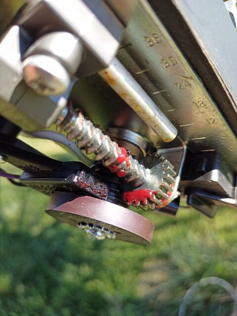
This is the inside of the Venture ma-810-24 actuator that I have. And as I said, worked fine last week.

venture.jpg
 
I will try the car battery tomorrow. Feeling it will probably make the motor move, I went ahead and ordered a replacement "super sensor ii" reed switch from ebay. The way these things are becoming rare, probably not a bad idea to have one on hand even if it's not the switch.
 
No panics. Do you have a multimeter? I hope so.

1) When you have someone command the ASC1 to go E or W. Meter across the motor terminals on the terminal strip and meter in DC volt mode. Do you see a brief increase in voltage across the terminals when it is ran either direction? Of course you will have to clear the error each time.

2) With the ASC1 off inside and meter in ohms mode.
Or.....simply disconnect the sensor connector wires leading into the house temporarily.
Slightly loosen the brown magnet screw so that it turns in your fingers. Slightly. You don't want the magnet to wobble.
Okay. Meter across the reed switch terminals (purple wires).
Spin the magnet in your fingers. The meter should fluctuate between infinite (0L) and very close to 0 (same as if the probe tips are shorted) as the magnet poles actuate the reed switch.
You can also check the reed switch wires inside at the ASC1 with them disconnected while someone watches the meter and you turn the magnet.
What do ya' got so far?

3) With the assumption that both microswitch limit switches are not tripped (plungers on them not depressed).
Unhook the motor wires going into the house. Put your meter on on the motor terminals in low ohms or diode mode.
Take a small screwdriver and make the plungers on the switches click. The meter should fluctuate between infinite and close to 0 ohms.
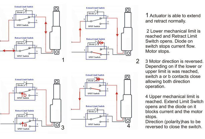
You may have to switch meter leads on the terminals as the diodes soldered across the microswitch terminals only let the pixies go one way.
You could also check directly across the switch leads. Just beware that you will probably have to check the switches again by reversing the meter probes. Diodes!

Next I would grab a 12v battery and wire it directly to the motor wires. Bypassing the limit switches. And look for motion.

Get back to us. Hope this helps.
 

Attachments

  • Limit_Switch.jpg
    Limit_Switch.jpg
    186.1 KB · Views: 127
1) When you have someone command the ASC1 to go E or W. Meter across the motor terminals on the terminal strip and meter in DC volt mode. Do you see a brief increase in voltage across the terminals when it is ran either direction? Of course you will have to clear the error each time.

Yes. Negative in one way and positive in the other. So that looks good.
2) With the ASC1 off inside and meter in ohms mode.
Or.....simply disconnect the sensor connector wires leading into the house temporarily.
Slightly loosen the brown magnet screw so that it turns in your fingers. Slightly. You don't want the magnet to wobble.
Okay. Meter across the reed switch terminals (purple wires).
Spin the magnet in your fingers. The meter should fluctuate between infinite (0L) and very close to 0 (same as if the probe tips are shorted) as the magnet poles actuate the reed switch.

I think this might be the issue. I did loosen it enough to turn but not to wobble --it only rotates in a limited direction either way, but I'm guessing that's normal. It was very close to 0, but no noticeable fluctuation, and definitely no 0L/infinite showed.

You can also check the reed switch wires inside at the ASC1 with them disconnected while someone watches the meter and you turn the magnet.

What do ya' got so far?
Wasn't sure about directions on this, but likely dish too far away to attempt this, anyway.


3) With the assumption that both microswitch limit switches are not tripped (plungers on them not depressed).
Unhook the motor wires going into the house. Put your meter on on the motor terminals in low ohms or diode mode.
Take a small screwdriver and make the plungers on the switches click. The meter should fluctuate between infinite and close to 0 ohms.
You may have to switch meter leads on the terminals as the diodes soldered across the microswitch terminals only let the pixies go one way.
You could also check directly across the switch leads. Just beware that you will probably have to check the switches again by reversing the meter probes. Diodes!

Yes, both fluctuated between 0L/infinite and close to 0 ohms. When 45 came up on the other switch, I reversed the leads and also got the infinite and 0 ohms fluctuation.

Next I would grab a 12v battery and wire it directly to the motor wires. Bypassing the limit switches. And look for motion.
Yes. Movement to west. Reversed leads and returned to the east.

What do you think? Bad sensor?
 
Okay. So we're getting voltage outside until the ASC1 says oops no sensor pulses detected and it shuts of motor juice. Check.

The sensor magnet is segmented like a pie. It escapes me. All outside rim in 6 segments (or 4??) with alternating N-S poles or all the same....N-N-N or S-S-S. A small kiddy compasss would tell fast.
Anyways. Even if you take the magnet loose and run it past the reed switch you should get it to open and close like turning the kitchen light on and off with a magnet instead of a finger.
Bad reed switch? Could be. To go farther we need that thing to go open circuit (like the meter leads are separated) or closed circuit....'shorted'.
By chance are you getting a large amount of magnet shaft play when you push and pull it a little?
 
  • Like
Reactions: northgeorgia
Yes. Movement to west. Reversed leads and returned to the east.

What do you think? Bad sensor?
To verify if the reed switch is providing pulse counts:

When driving the motor with the 12vdc battery, use the continuity tester to the reed switch's purple and brown leads. Do you observe open / close cycles on the meter as the motor is run east and west?

You stated in an earlier post that the ASC1 movement produces "Reach W/E Limit! Limit Switch? Sensor? Motor Blocked? message." And also "Tried using a VBOX7, and I got an Err2 message." I would suggest that these tests along with the confirmed motor East / West movement with the 12Vdc battery test points to a defective reed switch or sensor wiring.
 
  • Like
Reactions: northgeorgia
Rain is forecast for the week, then cold temperatures, then a conference to attend ... so I won't be able to do any more troubleshooting at the dish for a while. By then, the sensor may have arrived in the mail. Thanks for the advice. We'll await until the next weekend and see...
 
Replaced the sensor. Unfortunately, no change. How could I use the multimeter to make sure the ASC1 is delivering power on the reed sensors? The wiring I guess is the next suspect, but it's buried and I see no evidence of damage from the exposed sections. Is there a way to test this without digging it up (I don't really have any help, and the dish is a good 200 ft or so away)?
 
Last edited:
Replaced the sensor. Unfortunately, no change. How could I use the multimeter to make sure the ASC1 is delivering power on the reed sensors? The wiring I guess is the next suspect, but it's buried and I see no evidence of damage from the exposed sections. Is there a way to test this without digging it up (I don't really have any help, and the dish is a good 200 ft or so away)?
If you have a multimeter set it on low ohms if it has that selection.
Okay. Look at the display with the probes separated. What's your reading? That's open circuit.
You will get the same reading (at the switch) if you connect the probes to the reed switch wires.
IF the magnet wheel is positioned to allow the switch contacts to open.
That's the top image in the attachment.

Now. Short the meter leads. You should get close to 0 ohms resistance.
At the reed switch leads with the meter leads hooked to the wires and the magnet wheel spun to close the reed switch contacts. You should get very close to 0 ohms resistance too.
That's the bottom image.

With the switch leads on the correct terminal strip contacts that lead into the house.
Unhook the ASC1 wires from terminals 6. Put your meter leads on the loose wires.
Have the wifey look at the meter (show her what shes looking for). and go outside and spin the loosened magnet slowly. The meter should fluctuate like it did at the switch.
*Because of wire length you may not get 0 ohms resistance....maybe 1, 2 or so. But you should always get infinite (like the probes are separated) if the magnet lets the reed switch open......the top image.*

At the back of the ASC1 on terminals 6 you should be able to measure a slight voltage (Guys...how much?) in DC volts mode.
Out at the dish with the reed switch wires disconnected you should see close to the same voltage.

With the reed switch wires connected to the terminal strip and on the ASC1. Meter on DC volts on the terminals.
Spinning the magnet should show a voltage swing. Like alternating between close to 0 and up to 5VDC when you spin the magnet.

What you got?
 

Attachments

  • Reed_SW1.JPG
    Reed_SW1.JPG
    92.2 KB · Views: 110
  • Like
Reactions: phlatwound
Easy, just disconnect the sensor wires at both ends, twist one end together, then at the other end set a DVOM set to ohms across the non twisted end. Ideally a old analog ohm meter would work best as it would put a slight load on the circuit.
Thank you so much! Both sensor wires are in good condition. I also double checked the motor wires, and they are good.
 
If you have a multimeter set it on low ohms if it has that selection.
Okay. Look at the display with the probes separated. What's your reading? That's open circuit.
You will get the same reading (at the switch) if you connect the probes to the reed switch wires.
IF the magnet wheel is positioned to allow the switch contacts to open.
That's the top image in the attachment.
0.001 to 0.003

Now. Short the meter leads. You should get close to 0 ohms resistance.
At the reed switch leads with the meter leads hooked to the wires and the magnet wheel spun to close the reed switch contacts. You should get very close to 0 ohms resistance too.
That's the bottom image.
When shorted, yes, 0 ohms. Cannot "spin" wheel, even when loosened, so cannot test this.

With the switch leads on the correct terminal strip contacts that lead into the house.
Unhook the ASC1 wires from terminals 6. Put your meter leads on the loose wires.
Have the wifey look at the meter (show her what shes looking for). and go outside and spin the loosened magnet slowly. The meter should fluctuate like it did at the switch.
*Because of wire length you may not get 0 ohms resistance....maybe 1, 2 or so. But you should always get infinite (like the probes are separated) if the magnet lets the reed switch open......the top image.*
The problem is, I cannot freely spin the magnet. As seen in the photo, the magnet is part of a threaded piece that the metal gear interacts with. Loosing/removing the screw only allows the magnet wheel/thread piece to loosen from the shaft.


At the back of the ASC1 on terminals 6 you should be able to measure a slight voltage (Guys...how much?) in DC volts mode.
Out at the dish with the reed switch wires disconnected you should see close to the same voltage.
Interesting. I can measure around 10 at the ASC1. But attempting to move E or W shows no change in voltage. Did not attempt at dish.

With the reed switch wires connected to the terminal strip and on the ASC1. Meter on DC volts on the terminals.
Spinning the magnet should show a voltage swing. Like alternating between close to 0 and up to 5VDC when you spin the magnet.

What you got?
Cannot spin magnet.
 

Attachments

  • magnet.jpg
    magnet.jpg
    116.5 KB · Views: 104
  • Like
Reactions: arlo
0.001 to 0.003


When shorted, yes, 0 ohms. Cannot "spin" wheel, even when loosened, so cannot test this.


The problem is, I cannot freely spin the magnet. As seen in the photo, the magnet is part of a threaded piece that the metal gear interacts with. Loosing/removing the screw only allows the magnet wheel/thread piece to loosen from the shaft.


Interesting. I can measure around 10 at the ASC1. But attempting to move E or W shows no change in voltage. Did not attempt at dish.


Cannot spin magnet.
What if you happened to loosen the screw with the star washer a bit? The magnet should turn a little bit.
You're going to have to use a bit of intuition here buddy.
The idea is to get the magnet poles to go over the reed switch that's buried in the plastic.
It would be hard to believe that the magnet has demagnetized over time.
Take something light, like a sewing needle and pass it over the the magnet.
You should get several pie shaped (6??) areas of attraction.
Those areas when rotated over the reed switch must actuate the contacts and the meter goes to 0 ohms.
On-off-on-off-on-off. Like I said. Almost like gluing a piece of steel to the kitchen light switch and triggering it with a neodymium magnet very close but never touching it.
Makes more sense now?
 
My ASC1 had a stuck relay on two different occasions - years apart. It was an easy fix - open the bottom of the unit with an allan key (where rubber feet are) and gently tap the relays inside.

The difference in my case was that it was only one relay and it would move in one direction. Worth checking if all other tests check out.
 
What if you happened to loosen the screw with the star washer a bit? The magnet should turn a little bit.
You're going to have to use a bit of intuition here buddy.

I loosened the screw so much that it did come out, and the magnetic wheel slid further down the shaft. But it still would not rotate left or right. I guess I could have tried to take the magnet off, but I figured we're trying to rotate it and not remove it entirely.
The idea is to get the magnet poles to go over the reed switch that's buried in the plastic.
It would be hard to believe that the magnet has demagnetized over time.
I wouldn't think so, either. After all, everything worked two weeks ago.

Take something light, like a sewing needle and pass it over the the magnet.
You should get several pie shaped (6??) areas of attraction.
Those areas when rotated over the reed switch must actuate the contacts and the meter goes to 0 ohms.
On-off-on-off-on-off. Like I said. Almost like gluing a piece of steel to the kitchen light switch and triggering it with a neodymium magnet very close but never touching it.
Makes more sense now?
Yes, but I'm not sure how to do it with this magnet. I may have to use a refrigerator magnet to try this. It's not rotating at all.
 
I loosened the screw so much that it did come out, and the magnetic wheel slid further down the shaft. But it still would not rotate left or right. I guess I could have tried to take the magnet off, but I figured we're trying to rotate it and not remove it entirely.

I wouldn't think so, either. After all, everything worked two weeks ago.


Yes, but I'm not sure how to do it with this magnet. I may have to use a refrigerator magnet to try this. It's not rotating at all.
So take the screw all the way out and pull the disc. Not sure if it's keyed to the shaft.
One thing to note. Using too strong of a magnet on a reed switch can screw it up too.
 
My ASC1 had a stuck relay on two different occasions - years apart. It was an easy fix - open the bottom of the unit with an allan key (where rubber feet are) and gently tap the relays inside.

The difference in my case was that it was only one relay and it would move in one direction. Worth checking if all other tests check out.
Interesting. I haven't thought of that. I think I've done this before with a v-box; sometimes it would work -- sometimes not. Anyone have a photo or diagram of where these are in the ASC1 (I'll have to find an allen wrench to do this -- what size, do you remember off hand)? Gone for a few days for work, so will have to try out some of these suggestions towards the end of the week.
 
Interesting. I haven't thought of that. I think I've done this before with a v-box; sometimes it would work -- sometimes not. Anyone have a photo or diagram of where these are in the ASC1 (I'll have to find an allen wrench to do this -- what size, do you remember off hand)? Gone for a few days for work, so will have to try out some of these suggestions towards the end of the week.
Didn't we already determine there is a brief ~36 VDC pulse at the motor terminals when the E-W button is pressed before it errors out? You do realize that + & - is swapped at the terminals to get the motor to run the other direction, right?
I mean it's nothing to pull the motor off of the actuator shaft and bench it. Power it with a 12v battery and check if the reed switch is working. If the multimeter has a beep on ohms. Listen for a beep-beep when the motor runs and the magnet is turning. Of course with the meter leads on the reed terminals.
Let's stick with the program before going out on a tangent and ripping the ASC1 open.
Believe me. This ain't soyuz science.
 
  • Like
Reactions: primestar31

DisEqc Switch

Users Who Are Viewing This Thread (Total: 0, Members: 0, Guests: 0)

Who Read This Thread (Total Members: 2)