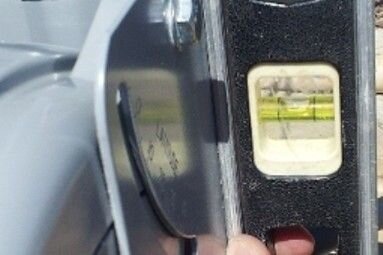
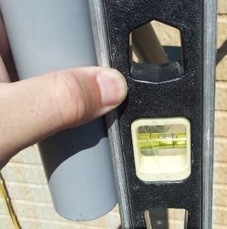
Earlier I'd made a post lamenting the poor performance of my SG9120B motor. It acted like it was binding, I could not adjust the backlash from the motor and it allowed too much movement to the dish. See this and this.
I decided to take the dish down and investigate the motor, and it would be a good time to methodically get a good install and aim on the dish. I was having troubles getting good tracking since first installation. I took the motor apart to see what was going on inside, mostly because the "M4" and "M3" adjusting screws didn't seem to be doing much.
This is what the interior looks like.
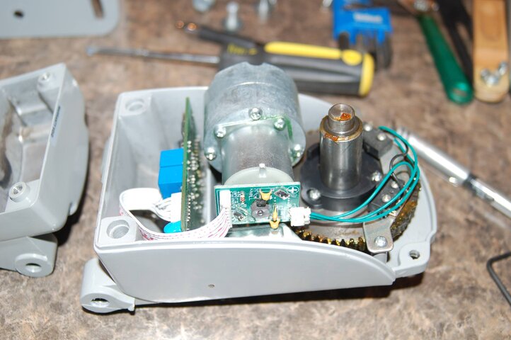
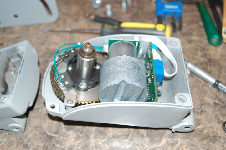
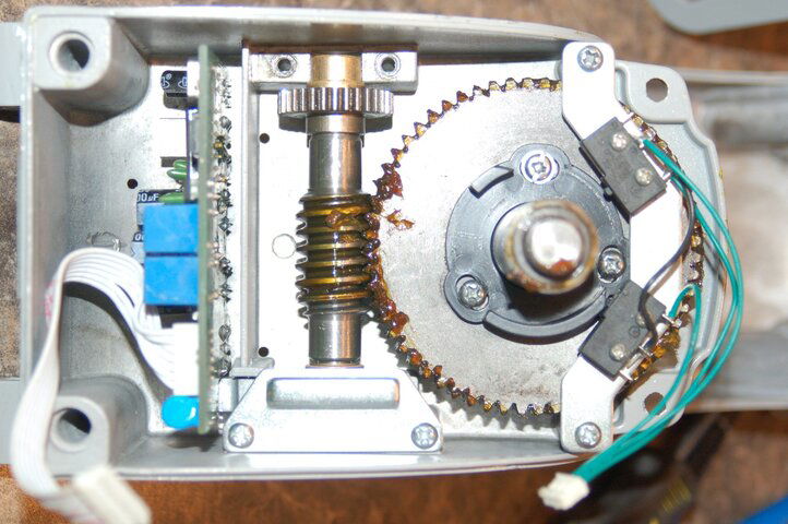
Two M4 cap screws held the motor and gear reduction to the case and worm shaft. After pulling the motor, you can see the worm drive to the main gear. The worm shaft is supported by a bronze bushing at each end, and the adjustment mechanism is opposite the worm shaft's spur gear.
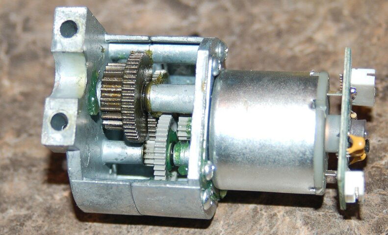
Here's the motor and reduction gearing. You can see the motor gear and several more gears into the gear train are plastic, then they are made of metal for the remainder of the drive. This means the higher speed/low stress gears are plastic, then they change to metal when the speeds get lower and the stresses higher.
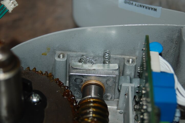
Next to come off is the two screws holding the plate on the adjusting machanism. It was apparent some spring pressure was there as the plate was backed off. I was just hoping to prevent one of those "snakes in a can" surprises! What I found under the plate was two springs, one apparently mangled during the manufacturing process.
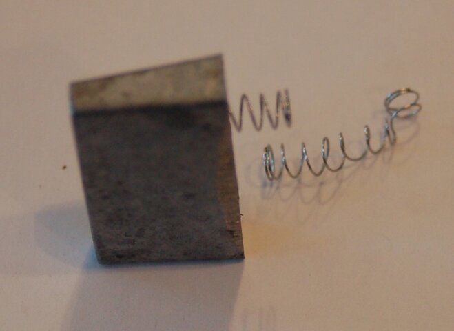
I pulled the springs and the wedge that they were held in...
...and the worm shaft assembly. You can see how the wedge will take up the end-play of the worm shaft. The smaller "currency" M3 adjusting screw prevents the wedge from seating too deep and binding the shaft from too little end play. This adjustment is important to prevent motion of the mounting tube that results from the worm shaft moving axially.
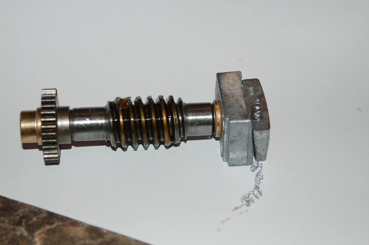
I needed to replace the mangles spring, so I grabbed two el cheapo Bic pens to rob the spring from. These springs were about 1/32 too large in diameter to seat into the wedge, so I drilled out the holes to accept the new springs. One hole was about 5 degrees from vertical, so that was corrected when boring out the holes.
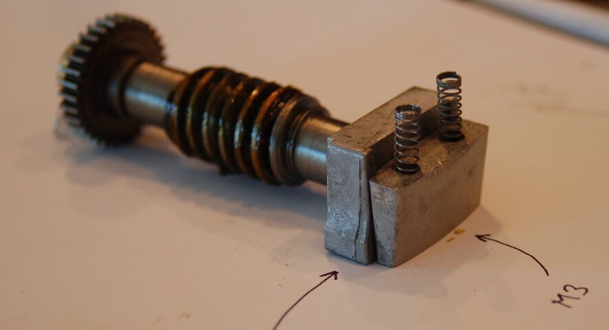
I also took the wedge to a sander to polish up the surfaces that are expected to slide when being adjusted. They were pretty rough and not really finished during manufacturing. 320 grit on a random orbital did wonders.
Here is a picture of the bell crank that the larger M4 adjusting screw pushes on. The bell crank pushes the whole bushing/wedge assembly and acts to adjust the worm shaft/worm towards the final drive gear, effectively setting the teeth engagement between the worm gear and final drive gear.
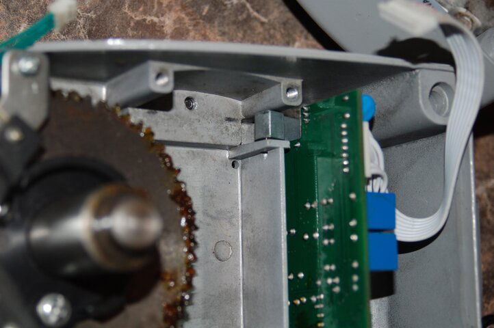
Here's a shot of the worm shaft back in the housing with the wedge, springs and bell crank in position.
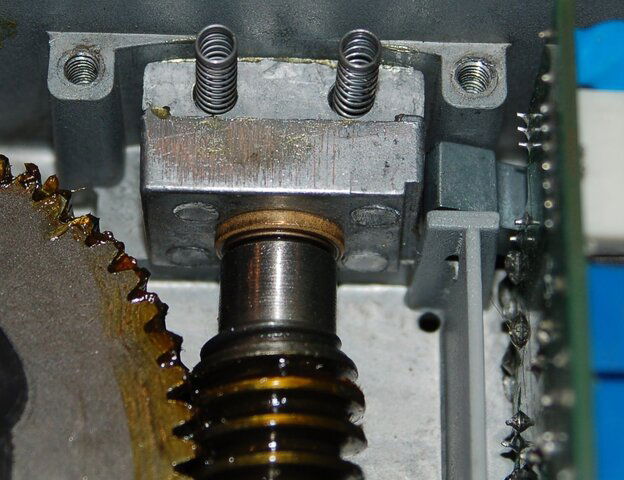
You can see the gap in the worm shaft with the adjusting wedge up.

With the wedge down, the gap goes away! This is one motion to adjust out to eliminate excess dish rotation via the M3 screw.
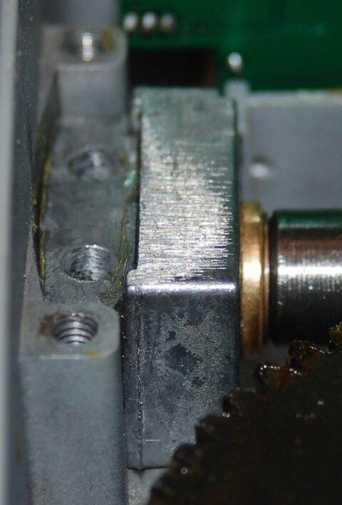
Everything went back together in reverse order, with some light machine oil (3-in-1) on the bushings. I put some grease on the wedge, but I'd probably not do that next time. The grease keeps the wedge from responding (sliding) freely, but it will move. Just have to have some patience when adjusting, as the spring pressure is all that is pushing to make it tight. The screw limits the wedge motion.
With the motor assembled and on the table, I tried to measure the current by connecting jumpers between the microHD and SG9120B. This just would not work. I don't know if the ammeter blocked or attenuated signals, but it just didn't work. I started adjusting (by ear) by putting the M3 screw all the way in to give the most end play to the worm shaft. Slowly screw in the M4 screw until the drive starts to labor a bit then back off 1/8 to 1/4 turn. Then unscrew the M3 until the wedge doesn't back out any more. I did this by backing out the screw 3 turns then running the motor end to end then running the screw back in until the wedge stopped moving. I left the wedge screw putting pressure on the wedge and called it good.
The motor now ran from end to end without binding and the backlash was practically zero. I could not detect any backlash when twisting it by hand. It felt like a great improvement over what I had before. Also, the end-play on the output shaft was non-existent. I couldn't feel anything when pushing/pulling. What an improvement!
Next up, putting this bad boy back on the pole. I'll follow up with what I discovered when mounting, with some tips that maybe some, both new and old, could benefit from. For now, let's just say it was easy to hit 30W through 125W when I was done, just like I thought it should be!
I decided to take the dish down and investigate the motor, and it would be a good time to methodically get a good install and aim on the dish. I was having troubles getting good tracking since first installation. I took the motor apart to see what was going on inside, mostly because the "M4" and "M3" adjusting screws didn't seem to be doing much.
This is what the interior looks like.


Two M4 cap screws held the motor and gear reduction to the case and worm shaft. After pulling the motor, you can see the worm drive to the main gear. The worm shaft is supported by a bronze bushing at each end, and the adjustment mechanism is opposite the worm shaft's spur gear.

Here's the motor and reduction gearing. You can see the motor gear and several more gears into the gear train are plastic, then they are made of metal for the remainder of the drive. This means the higher speed/low stress gears are plastic, then they change to metal when the speeds get lower and the stresses higher.

Next to come off is the two screws holding the plate on the adjusting machanism. It was apparent some spring pressure was there as the plate was backed off. I was just hoping to prevent one of those "snakes in a can" surprises! What I found under the plate was two springs, one apparently mangled during the manufacturing process.

I pulled the springs and the wedge that they were held in...

...and the worm shaft assembly. You can see how the wedge will take up the end-play of the worm shaft. The smaller "currency" M3 adjusting screw prevents the wedge from seating too deep and binding the shaft from too little end play. This adjustment is important to prevent motion of the mounting tube that results from the worm shaft moving axially.

I needed to replace the mangles spring, so I grabbed two el cheapo Bic pens to rob the spring from. These springs were about 1/32 too large in diameter to seat into the wedge, so I drilled out the holes to accept the new springs. One hole was about 5 degrees from vertical, so that was corrected when boring out the holes.

I also took the wedge to a sander to polish up the surfaces that are expected to slide when being adjusted. They were pretty rough and not really finished during manufacturing. 320 grit on a random orbital did wonders.
Here is a picture of the bell crank that the larger M4 adjusting screw pushes on. The bell crank pushes the whole bushing/wedge assembly and acts to adjust the worm shaft/worm towards the final drive gear, effectively setting the teeth engagement between the worm gear and final drive gear.

Here's a shot of the worm shaft back in the housing with the wedge, springs and bell crank in position.

You can see the gap in the worm shaft with the adjusting wedge up.

With the wedge down, the gap goes away! This is one motion to adjust out to eliminate excess dish rotation via the M3 screw.

Everything went back together in reverse order, with some light machine oil (3-in-1) on the bushings. I put some grease on the wedge, but I'd probably not do that next time. The grease keeps the wedge from responding (sliding) freely, but it will move. Just have to have some patience when adjusting, as the spring pressure is all that is pushing to make it tight. The screw limits the wedge motion.
With the motor assembled and on the table, I tried to measure the current by connecting jumpers between the microHD and SG9120B. This just would not work. I don't know if the ammeter blocked or attenuated signals, but it just didn't work. I started adjusting (by ear) by putting the M3 screw all the way in to give the most end play to the worm shaft. Slowly screw in the M4 screw until the drive starts to labor a bit then back off 1/8 to 1/4 turn. Then unscrew the M3 until the wedge doesn't back out any more. I did this by backing out the screw 3 turns then running the motor end to end then running the screw back in until the wedge stopped moving. I left the wedge screw putting pressure on the wedge and called it good.
The motor now ran from end to end without binding and the backlash was practically zero. I could not detect any backlash when twisting it by hand. It felt like a great improvement over what I had before. Also, the end-play on the output shaft was non-existent. I couldn't feel anything when pushing/pulling. What an improvement!
Next up, putting this bad boy back on the pole. I'll follow up with what I discovered when mounting, with some tips that maybe some, both new and old, could benefit from. For now, let's just say it was easy to hit 30W through 125W when I was done, just like I thought it should be!
Last edited:


