Went down to Skywalker today and told my buddy there that the LNB power boosters had not worked as well as I wanted because of the extra connection involved and the signal loss that comes with it.
I asked for a powered 3x4 multi-switch. Told him what I was trying to achieve with standard C-Band/Ku Band LNBs and their need of more than 15V.
I told him about the modification my neighbor had done on the other power boosters and he understood.
We put a meter on it before I left and it only showed 11.9 V on the 13V side. So I asked if it were possible to modify this switch, and he said sure.
My neighbor across the street was busy tonight and won't be available until tomorrow evening.
I need to learn how to do this myself. I think it can be done pretty simply. I don't want to interfere with the signal, or mess up the switching which I think is all done on the other side of the board on the receiver input side.
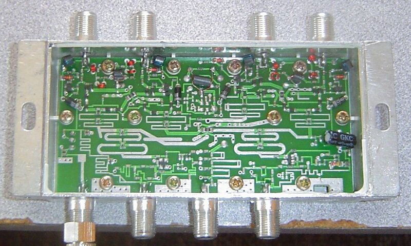
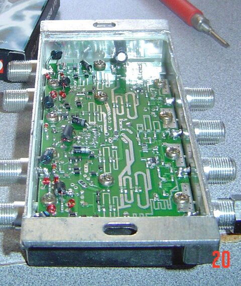
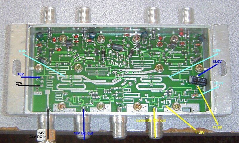
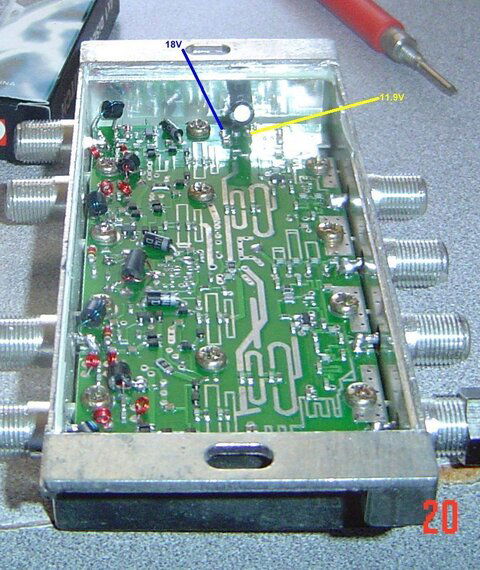
Here are pics with voltages marked.
Where do I "cut the trace" and where do I run the jumper from?


Just point me in the right direction.
Thanks for your help!
I asked for a powered 3x4 multi-switch. Told him what I was trying to achieve with standard C-Band/Ku Band LNBs and their need of more than 15V.
I told him about the modification my neighbor had done on the other power boosters and he understood.
We put a meter on it before I left and it only showed 11.9 V on the 13V side. So I asked if it were possible to modify this switch, and he said sure.
.just cut the 13v trace on the board and run a jumper from the last known source of the 18V
My neighbor across the street was busy tonight and won't be available until tomorrow evening.
I need to learn how to do this myself. I think it can be done pretty simply. I don't want to interfere with the signal, or mess up the switching which I think is all done on the other side of the board on the receiver input side.
Here are pics with voltages marked.
Where do I "cut the trace" and where do I run the jumper from?


Just point me in the right direction.
Thanks for your help!


